
Context-adaptive variable length coder with simultaneous storage of incoming data and generation of syntax elements

a variable length coder and data storage technology, applied in the field of variable length coding apparatus for compressing image signals, can solve the problems of time-consuming and long processing time of variable length coding processes, and achieve the effect of increasing processing speed

Active Publication Date: 2011-03-08
CANON KK
View PDF4 Cites 0 Cited by
  • Summary
  • Abstract
  • Description
  • Claims
  • Application Information

AI Technical Summary

Benefits of technology

[0010]The present invention has been made in consideration of the above situation, and has as its object to increase the processing speed even when a plurality of syntax elements depend one each other.

Problems solved by technology

In this variable-length coding apparatus described in Japanese Patent Laid-Open No. 2004-056758, however, a plurality of syntax elements depend on each other, so the processing takes a long time if coding of a second syntax element cannot be started before the calculation of a first syntax element is completed.
This makes the variable-length coding process time-consuming.

Method used


Image

  • Context-adaptive variable length coder with simultaneous storage of incoming data and generation of syntax elements
  • Context-adaptive variable length coder with simultaneous storage of incoming data and generation of syntax elements
  • Context-adaptive variable length coder with simultaneous storage of incoming data and generation of syntax elements

Examples


first embodiment

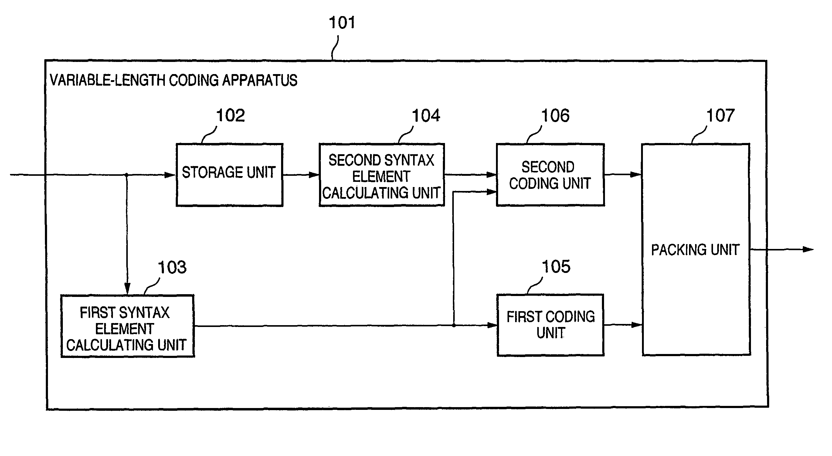
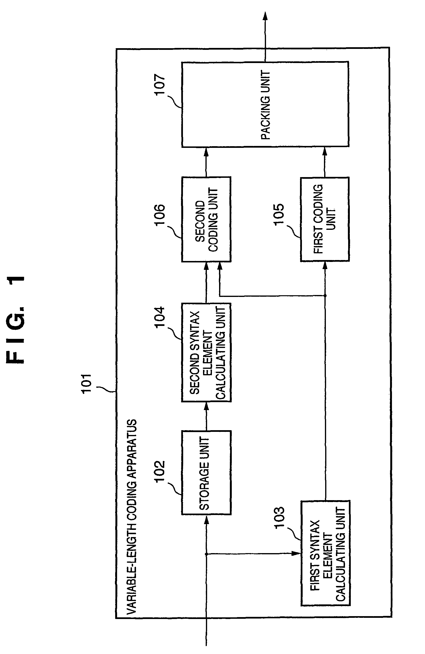
[0044]FIG. 1 is a view showing the arrangement of the first embodiment of the present invention.

[0045]Referring to FIG. 1, a variable-length coding apparatus 101 according to the first embodiment includes a storage unit 102, first syntax element calculating unit 103, second syntax element calculating unit 104, first coding unit 105, second coding unit 106, and packing unit 107. The packing unit 107 packs variable-length coded data.

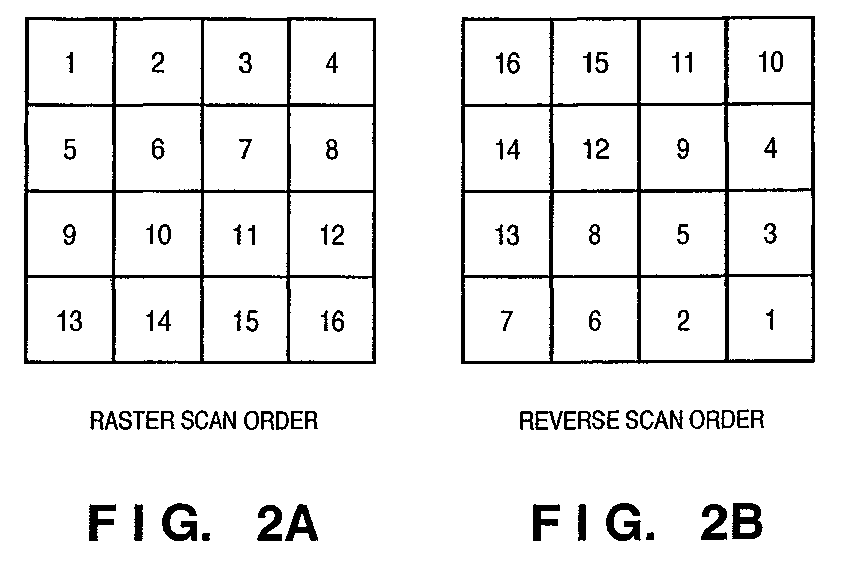
[0046]Image data of 4×4 rectangular blocks is input in a raster scan order shown in FIG. 2A to the variable-length coding apparatus 101.

[0047]The storage unit 102 is a RAM which temporarily stores the image data. Note that read or write to this RAM requires one cycle.

[0048]The first syntax element calculating unit 103 reads the image data in a block, calculates TotalCoeff, TrailingOnes, and TotalZeros in the block, and internally holds the calculated syntax elements.

[0049]The second syntax element calculating unit 104 reads out the image data held in the s...

second embodiment

[0098]The second embodiment of the present invention will be described below.

[0099]The second embodiment differs from the first embodiment in the following respect. In the first embodiment, the first syntax element calculating unit calculates the values of the first syntax elements directly from image data input to the storage unit. In the second embodiment, however, the value of additional information is calculated from image data, and a first syntax element calculating unit calculates the values of first syntax elements by using this additional information and data read out from a storage unit.

[0100]FIG. 11 is a view showing the arrangement of the second embodiment of the present invention. Referring to FIG. 11, a variable-length coding apparatus 1101 according to the present invention includes a storage unit 1102, first syntax element calculating unit 1103, second syntax element calculating unit 1104, first coding unit 1105, second coding unit 1106, and packing unit 1107. The pac...


PUM


Abstract

A variable-length coding apparatus which receives image data block by block, and generates coded data from syntax elements. A storage unit temporarily stores the image data, while, at the same time, a first syntax element calculating unit calculates a first syntax element from the image data. A first coding unit generates coded data of the first syntax element from a value of the first syntax element. A second syntax element is calculated from the image data by a second syntax element calculating unit that reads out the image data stored in the storage unit. A second coding unit generates coded data of the second syntax element on the basis of the values of the first and second syntax elements, and a packing unit connects the coded data of the first and second syntax elements.

Description

FIELD OF THE INVENTION[0001]The present invention relates to a variable-length coding apparatus for compressing an image signal.BACKGROUND OF THE INVENTION[0002]Recently, a method called H.264 is standardized as a motion image compression coding method. This H.264 coding method requires a larger operation amount than those of the conventional compression coding methods such as MPEG2 and MPEG4, but can realize a higher coding efficiency than those of these conventional methods.[0003]In this H.264 coding method, a context adaptive variable-length coding (CAVLC) method is defined as a variable-length coding method. Syntax elements which form a coded stream in the CAVLC method are the number of nonzero data (to be referred to as TotalCoeff hereinafter) in a block, the number of zero data (to be referred to as TotalZeros hereinafter) input before the last nonzero data in a block, the number of data (to be referred to as TrailingOnes hereinafter) having an absolute value of 1 and input af...

Claims


Application Information

Patent Timeline
Patent Type & Authority Patents(United States)
IPC IPC(8): H04N7/26H03M7/40H04N19/00H04N19/93
CPCH03M7/42H04N19/91H04N19/42H04N19/436H04N19/176H04N19/13H04N19/93
Inventor SUZUKI, KOICHI
Owner CANON KK
Learn More