Filament winding apparatus

a technology of winding apparatus and filament, which is applied in the direction of web handling, inductance/transformer/magnet manufacturing, transportation and packaging, etc., can solve the problems of requiring a large amount of time and a large barrier, and achieve the effect of enhancing the productivity of winding products such as pressure containers, saving manufacturing costs, and high quality

Active Publication Date: 2011-03-15
MURATA MASCH LTD
View PDF11 Cites 10 Cited by
  • Summary
  • Abstract
  • Description
  • Claims
  • Application Information

AI Technical Summary

Benefits of technology

[0007]In order to overcome the problems described above, the present invention provides a filament winding apparatus equipped with a hoop winding device that efficiently performs the hoop winding process in a short period of time.
[0011]The filament winding apparatus of the present invention is equipped with a hoop winding device and a helical winding device, so that a hoop winding process and a helical winding process can be efficiently performed in dedicated devices. The hoop winding device is configured by the rotatably-driven wrapping table, a plurality of bobbins that rotate with the wrapping table, and the guide member that moves and guides the fiber bundle to the mandrel. The plurality of fiber bundles are simultaneously wound to the mandrel at high speed by rotatably driving the wrapping table. The hoop winding process can be performed with the helical winding device and the mandrel connected with the fiber bundle and without rotating the mandrel by winding the fiber bundle to the mandrel while rotatably driving the wrapping table, whereby the winding of the fiber bundle with respect to the mandrel can be efficiently performed at high speed. Therefore, the hoop winding process can be terminated in a short period of time, the productivity of a winding product such as a pressure container is enhanced, and manufacturing costs are saved relative to a conventional device that hoop winds or helical winds the fiber bundle with a single winding head.
[0012]According to the hoop winding device in which the bobbins are arranged at equal intervals on a circumference having a center of rotation of the wrapping table as a center, and a tensor that adjusts a tensile force of the fiber bundle is arranged on the wrapping table facing a movement path of the fiber bundle between the bobbin and the mandrel, an appropriate back tension is applied to the fiber bundle wound to the mandrel. Thus, even when winding the fiber bundle to the mandrel at high speed, the fiber bundle is constantly applied with an appropriate tensile force and is wrapped to the mandrel, and a hoop winding process of high quality is performed.
[0013]According to the hoop winding device in which an application device that applies resin to the fiber bundle, and an adhesion sensor that detects an adhesion state of the resin on the fiber bundle, are arranged on the wrapping table facing the movement path of the fiber bundle, the chances of contact between the fiber bundle applied with resin and the guide member are minimized. Thus, the resin adhesion amount with respect to the fiber bundle is stabilized, and furthermore, the trouble necessary for maintenance of the guide member that moves and guides the fiber bundle is alleviated.

Problems solved by technology

As described above, hoop winding and helical winding are carried out with one type of winding head in a conventional filament winding apparatus, and thus a great amount of time is inevitably required for the process of winding the fiber bundle on the mandrel, which becomes a great barrier in manufacturing pressure containers and the like.

Method used


Image

  • Filament winding apparatus
  • Filament winding apparatus
  • Filament winding apparatus

Examples


Embodiment Construction

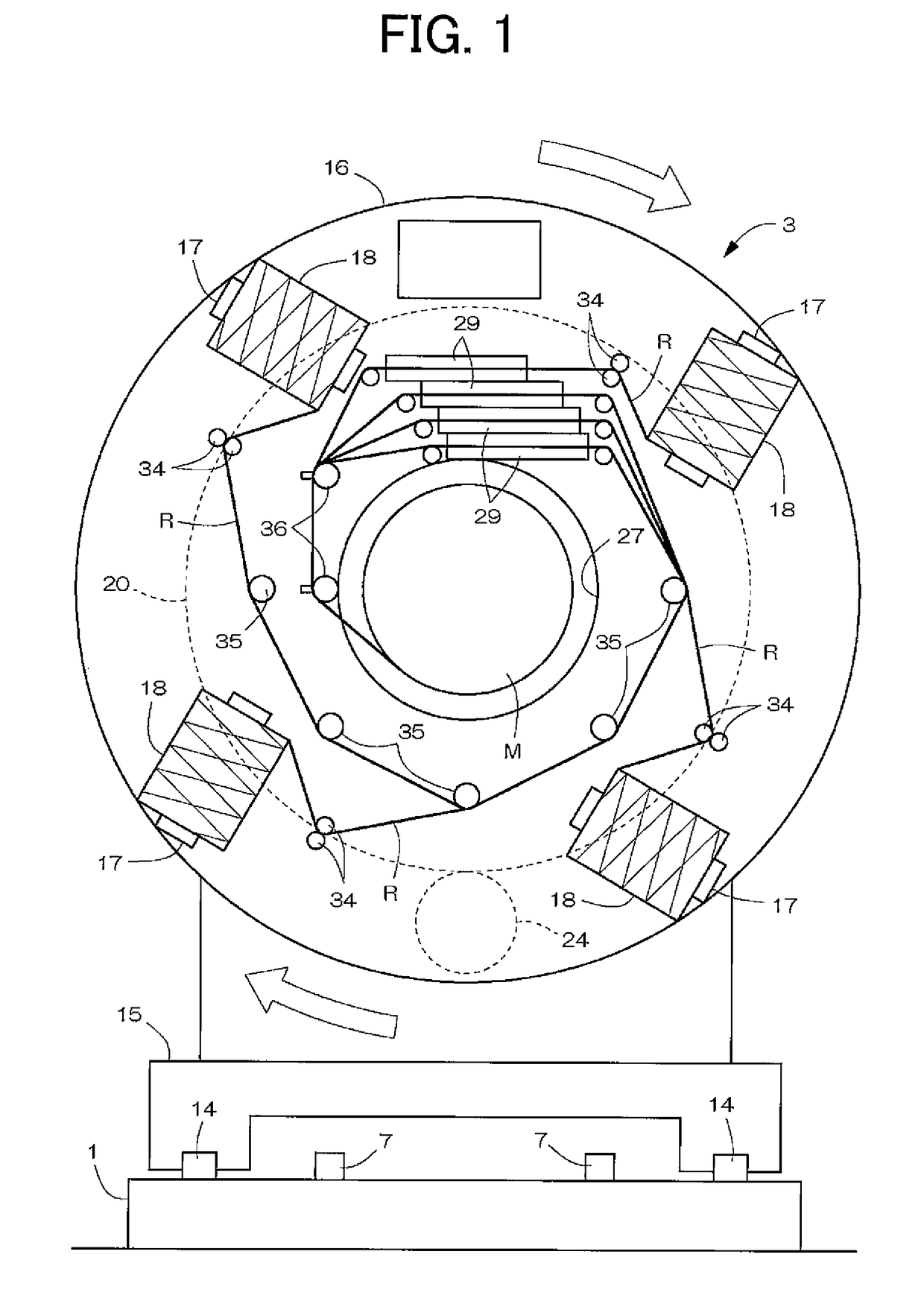
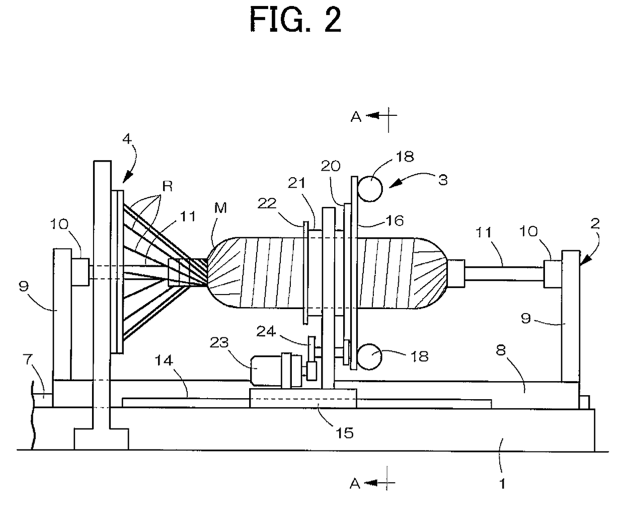
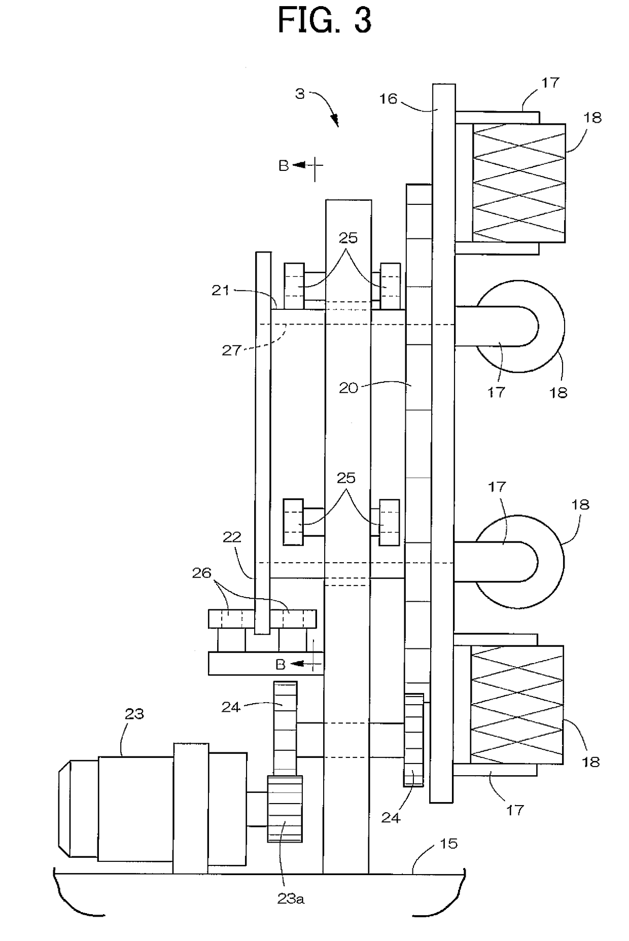
[0024]FIGS. 1-8 show examples of a filament winding apparatus according to the present invention. As illustrated in FIG. 2, the filament winding apparatus is configured by a fiber bundle supply structure and a winding device. The winding device comprises a supporting board 2 that is arranged on an upper part of a mount 1, which extends lengthwise in a left and right direction, and that supports a mandrel M; a hoop winding device 3; a helical winding device 4; and a mandrel replacing device. The supporting board 2 and the hoop winding device 3 are driven by a drive mechanism in a freely reciprocating manner along a longitudinal direction of the mount 1. The helical winding device 4 is fixed at a central position of the mount 1, and feeds and guides a fiber bundle R fed from a group of quills supported by the fiber bundle supply structure to the mandrel M.

[0025]The mandrel M, in a case where the final product is a pressure container, is formed to a container shape with a metal materia...


PUM

PropertyMeasurementUnit
circumferenceaaaaaaaaaa
tensile forceaaaaaaaaaa
adhesionaaaaaaaaaa

Abstract

A filament winding apparatus includes a hoop winding device and a helical winding device. The hoop winding device includes a disc-shaped wrapping table, a drive mechanism that rotatably drives the wrapping table, four bobbins supported along a peripheral edge of the wrapping table, and a guide member that moves and guides a fiber bundle fed from the bobbin to a mandrel arranged in an insertion hole of the wrapping table. The bobbin is axially supported in a freely rotatable manner with a chuck of a holder fixed to the wrapping table. A ratchet mechanism, which prevents over-rotation in a fiber bundle feeding direction of the bobbin, is arranged between the holder and the chuck.

Description

RELATED APPLICATIONS[0001]This application claims the benefit of priority under 35 USC 119 of Japanese patent application no. 2007-232975, filed on Sep. 7, 2007, the entire contents of which are incorporated herein by reference.BACKGROUND OF THE INVENTION[0002]1. Field of the Invention[0003]The present invention relates to a filament winding apparatus equipped with a hoop winding device and a helical winding device and, in particular, to an improved hoop winding device.[0004]2. Description of the Related Art[0005]When forming a pressure container by a filament winding method, a fiber bundle is hoop wound or helical wound on a mandrel to form a reinforcement layer (see Japanese Laid-Open Patent Publication No. 10-119138, paragraphs 0022 to 0023, FIG. 1). In a conventional general filament winding apparatus, the fiber bundle is hoop wound or helical wound with one type of winding head.[0006]As described above, hoop winding and helical winding are carried out with one type of winding h...

Claims


Application Information

Patent Timeline
Patent Type & Authority Patents(United States)
IPC IPC(8): B21C47/14
CPCB29C53/70B29C53/8016B29C53/8066
Inventor UOZUMI, TADASHITAKASHIMA, HIROKITANIGAWA, MOTOHIRO
Owner MURATA MASCH LTD
Why Eureka
Try Eureka