Brake-pressure modulator pilot unit

a pilot unit and modulator technology, applied in the direction of fluid pressure control, process and machine control, instruments, etc., can solve the problems of reducing the achievable air flow and the inability of the pilot control circuit according to d2 at any given moment, and reducing the airflow

Active Publication Date: 2011-03-15
WABCO EURO BVBA SPRL
View PDF15 Cites 26 Cited by
  • Summary
  • Abstract
  • Description
  • Claims
  • Application Information

AI Technical Summary

Benefits of technology

[0008]Still other objects and advantages of the present invention will in part be obvious and will in part be apparent from the specification.
[0009]The present invention accordingly comprises the featur

Problems solved by technology

However, the pilot-control circuit according to D2 suffers from the disadvantage that it is not possible at any given instant to admit air via one of the two ducts while venting via the other.
A further disadvantage of this solution lies in the series connection of the valves, meaning that the achievable air flow is diminished and the effective nominal width of the pilot-control unit is reduced.
As explained below, however, the principle of different design of the restoring springs (13, 17) that underlies this valve for ind

Method used


Image

  • Brake-pressure modulator pilot unit
  • Brake-pressure modulator pilot unit
  • Brake-pressure modulator pilot unit

Examples


Embodiment Construction

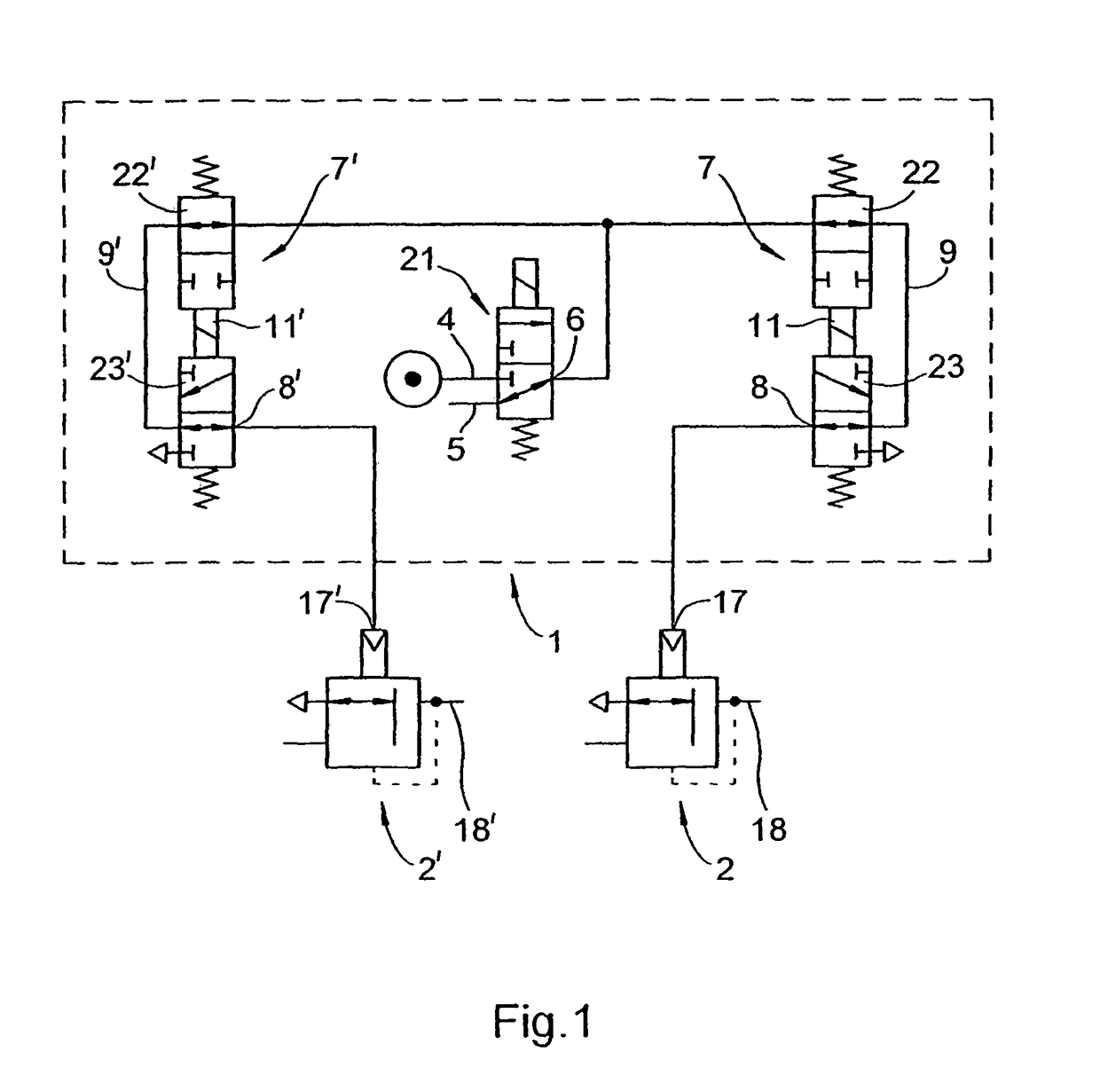
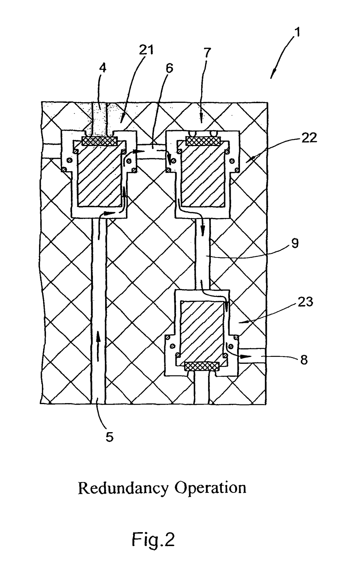
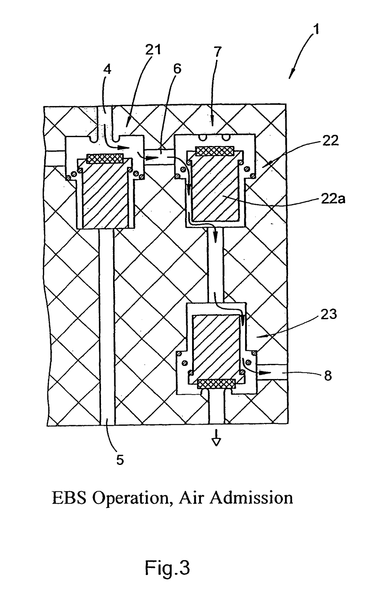
[0021]Referring now to the drawings where (non-ferromagnetic) parts that are not magnetically conductive are illustrated with cross hatching, so that they can be readily distinguished from singly-hatched magnetic parts, and wherein reference numerals 1, 2, 4, 5, 6, 17, 18, 21, 22 and 23 are adopted from D2 for identification of devices having like effects, FIG. 1 shows a pneumatic valve control device (1) according to one embodiment of the present invention, which in particular is used as a pilot-control unit for an electronic air-brake system. Valve control device (1) is capable of making a pilot-control pressure available for two different brake-pressure-regulating loops, designated hereinafter as the first and second brake-pressure-regulating loops.

[0022]In this pilot-control unit, a 3 / 2 solenoid valve (21) with two inputs (4, 5) and one output (6) is used as the redundancy valve, while a first valve-modulator device (7) is used for the first brake-pressure-regulating loop and a ...


PUM


Abstract

A valve control unit including three valve units for two brake channels of an electropneumatic brake system is provided. Each valve unit is embodied as a valve modulator device for a braking pressure control circuit including an air inlet valve with a primary solenoid and a bleed valve with a secondary solenoid. Each modulator device armature includes a common solenoid guide arrangement controlled by the magnetic flux of a common magnetic coil. Independent operation of the armatures is achieved whereby flux through the secondary solenoid is weakened by a shunt in the flux circuit which causes a switching delay for the secondary solenoid relative to the primary solenoid. The magnetic resistance of a non-magnetic disc effects switch-off acceleration in the flux circuit with energized secondary solenoid, weakens the field and causes the secondary solenoid to revert to a spring-loaded base state at a higher flux than the primary solenoid.

Description

BACKGROUND OF THE INVENTION[0001]The present invention relates to an improved valve pilot-control unit for a brake-pressure modulator.[0002]DE 100 09 116 A1 (hereinafter, “D1”) describes a known valve device for the pilot-control unit of a brake-pressure modulator for an electronic air-brake system (EBS). As shown in FIG. 2 of D1, the pneumatic circuit for the pilot-control unit of a brake-regulating loop of the brake-pressure modulator comprises a 3 / 2 solenoid valve (21) as a redundancy valve, a normally open 2 / 2 solenoid valve (22) as an air-admission valve and a normally open 2 / 2 solenoid valve (23) as a vent valve. As described in DE 42 27 084 A1 (see FIG. 2 therein), the redundancy valve in such circuit can also be used commonly for a second brake-regulating loop. According to this circuit layout, therefore, the pilot-control unit for two brake-regulating loops comprises one 3 / 2 redundancy valve for both loops and separate 2 / 2 vent valves and 2 / 2 air-admission valves for each i...

Claims


Application Information

Patent Timeline
IPC IPC(8): B60T8/34B60T8/32
CPCB60T8/327B60T8/362B60T15/027Y10T137/87917Y10T137/88005
Inventor FRANK, DIETERROVIRA-RIFATERRA, JUANSIEKER, ARMINTEICHMANN, ANDREAS
Owner WABCO EURO BVBA SPRL
Why Eureka
Try Eureka