Developing roller and imaging apparatus using the same

a technology of imaging apparatus and roller, applied in the direction of electrographic process apparatus, instruments, optics, etc., can solve the problems of voluminous space, cost of installation, quality problems, etc., and achieve the effect of reducing ultraviolet amount, and promoting ultraviolet curing reaction

Inactive Publication Date: 2011-03-15
BRIDGESTONE CORP
View PDF23 Cites 23 Cited by
  • Summary
  • Abstract
  • Description
  • Claims
  • Application Information

AI Technical Summary

Benefits of technology

[0043]The ultraviolet initiator has a maximum wavelength of not less than 400 nm in the ultraviolet absorption wavelength zone, so that a long wavelength ultraviolet ray of not less than 400 nm can arrive at the inside of the resin layer and hence the ultraviolet curing reaction can be promoted while supplementing the reduction of ultraviolet amount at the inside of the layer through the carbon-based electrically conducting agent. Therefore, it is possible to use carbon-based materials as the electrically conducting agent to be included in the ultraviolet-curing type resin in view of various advantageous points.
[0044]The ultraviolet initiator has a maximum wavelength of less than 400 nm in the ultraviolet absorption wavelength zone, so that the curing reaction of the resin can be effectively promoted even in a portion near to the surface of the layer through the action of a short wavelength ultraviolet ray having a maximum wavelength of less than 400 nm.
[0045]The ultraviolet-curing type resin is formed by applying the solution of a solvent-free resin composition and curing through the irradiation of the ultraviolet ray, so that large-scale installation and space for the drying can be reduced as compared with the formation by drying and curing with heat or hot air instead of the irradiation of the ultraviolet ray, and also the resin layer can be formed in a higher precision while suppressing the scattering of the layer formation due to the fact that the control of the drying process is difficult.
[0046]At least one layer of the resin layers arranged on the outside of the shaft member is constituted with the electron beam curing type resin containing an electrically conducting agent, so that the drying line in the formation of the resin layer can be made useless, and the carbon-based material can be used as the electrically conducting agent capable of giving the electric conductivity to the resin layer without contaminating the latent image support different from the case of using the ultraviolet-curing type resin.
[0047]The electron beam curing type resin is formed by applying the solution of a solvent-free resin composition and curing through the irradiation of the electron beam, so that large-scale installation and space for the drying can be reduced as compared with the formation by drying and curing with heat or hot air instead of the irradiation of the electron beam, and also the resin layer can be formed in a higher precision while suppressing the scattering of the layer formation due to the fact that the control of the drying process is difficult.
[0048]The resin layer is constituted with two or more layers, and the volume resistivity of a second resin layer located at the radially outermost side is not less than 1010 Ω·cm and the volume resistivity of a first resin layer adjoining to the inner side of the second resin layer is not more than 106 Ω·cm, so that the poor imaging such as image fogging, uneven image, ghost image or the like due to the fact that the charging ability to the developing agent is insufficient, or the poor imaging due to the developing agent attached to the developing roller can be suppressed sufficiently. Moreover, these facts are found out as a results of various experiments by the inventors.

Problems solved by technology

For this end, a long drying line is required for the mass production of the developing roller 91, and hence the cost required for the installation and space becomes voluminous.
Also, the resin layer is required to have an electric conductivity and surface state controlled in a high precision from its applications, but the scattering in the temperature distribution and air flow amount in the drying line largely affects these performances and hence there is a problem in the quality.

Method used


Image

  • Developing roller and imaging apparatus using the same
  • Developing roller and imaging apparatus using the same
  • Developing roller and imaging apparatus using the same

Examples


examples

[0210]Next, the invention will be concretely explained with reference to the following examples and comparative examples, but the invention is not limited thereto.

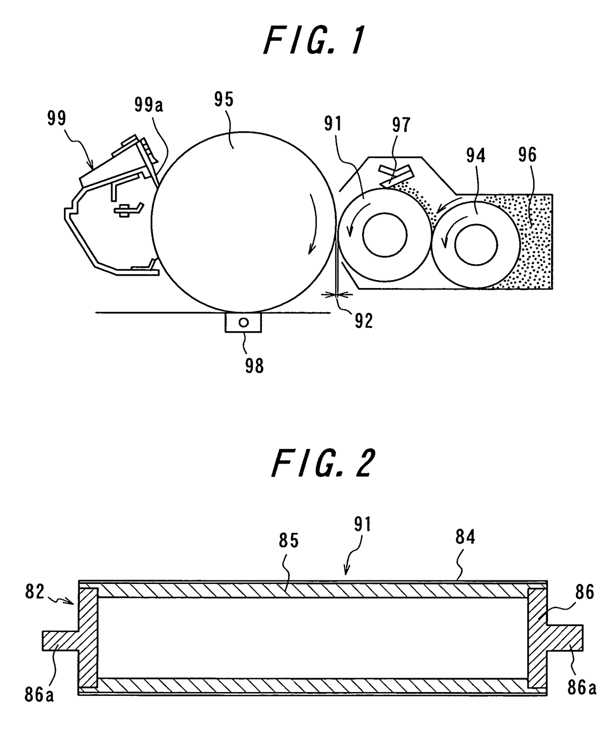
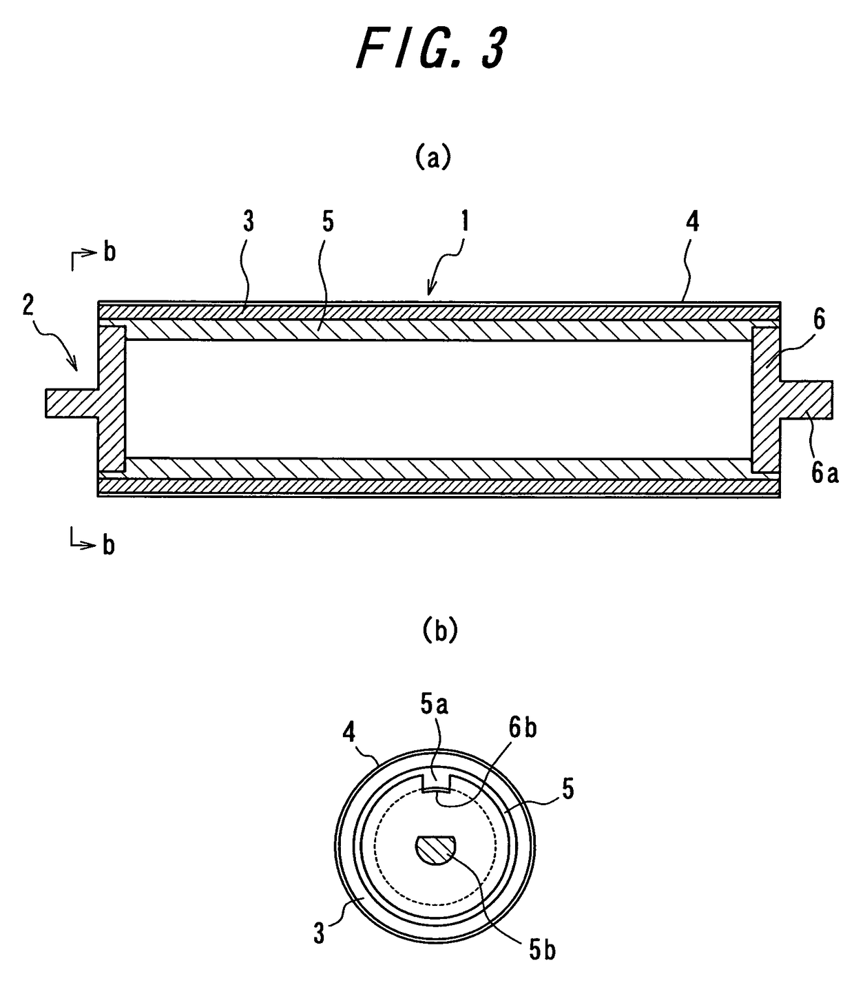
[0211]In the examples, the developing roller having a structure shown in FIG. 3 is produced by directly forming the resin layer on the shaft member of aluminum pipe when the developing roller is not provided with the elastic layer, or by forming the elastic layer on the shaft member and thereafter forming the resin layer thereon when the developing roller is provided with the elastic layer. For the comparison with the developing roller of the example, there is prepared a developing roller having a construction partly different from that of the invention as a comparative example. With respect to the developing rollers of the examples and the comparative examples, the characteristics of the roller and the image are evaluated.

[0212]In a material table showing materials used for the formation of the resin layer and item-evalua...


PUM

PropertyMeasurementUnit
volume resistivityaaaaaaaaaa
particle sizeaaaaaaaaaa

Abstract

A developing roller includes an ultraviolet-curing type resin layer and using a carbon-based electrically conducting agent for giving an electrical conductivity to the resin layer, as well as an imaging apparatus using the same. The developing roller 1 includes a shaft member 2 of a metal pipe and a resin layer 4. The resin layer 4 is a resin having fine particles dispersed therein, wherein the ratio a / b of average particle size of fine particles a to total thickness of resin layers b is greater than 2.0 and less than or equal to 5.0.

Description

TECHNICAL FIELD[0001]This invention relates to a developing roller used in an imaging apparatus such as an electrophotographic apparatus, e.g. a copier, a printer or the like, an electrostatic recording apparatus and so on as well as an imaging apparatus using such a developing roller.RELATED ART[0002]In the imaging apparatus of an electrophotographic system such as a copier, a printer or the like, a non-magnetic developer (toner) is fed to a latent image support such as a photosensitive drum keeping a latent image to visualize the latent image through the toner attached to the latent image on the latent image support. As a general one of such developing methods, there is a non-magnetic jumping development process wherein a charged toner is carried on an outer periphery of a developing roller arranged at a slight gap to a latent image support and the developing roller is rotated at a state of applying a voltage between the latent image support and the developing roller to jump the t...

Claims


Application Information

Patent Timeline
Patent Type & Authority Patents(United States)
IPC IPC(8): G03G15/08
CPCG03G15/0818
Inventor TAKAGI, KOJIAKAMA, SHUYOU
Owner BRIDGESTONE CORP
Why Eureka
Try Eureka