
Hybrid cycle rotary engine

a rotary engine and hybrid technology, applied in the field of hybrid cycle rotary engine, can solve the problems of too low maximum efficiency, difficult and costly control, and polluted hcci cycle engine, and achieve the effect of increasing the pressure and enhancing the formation of turbulen

Active Publication Date: 2011-03-22
LIQUIDPISTON INC
View PDF31 Cites 20 Cited by
  • Summary
  • Abstract
  • Description
  • Claims
  • Application Information

AI Technical Summary

Benefits of technology

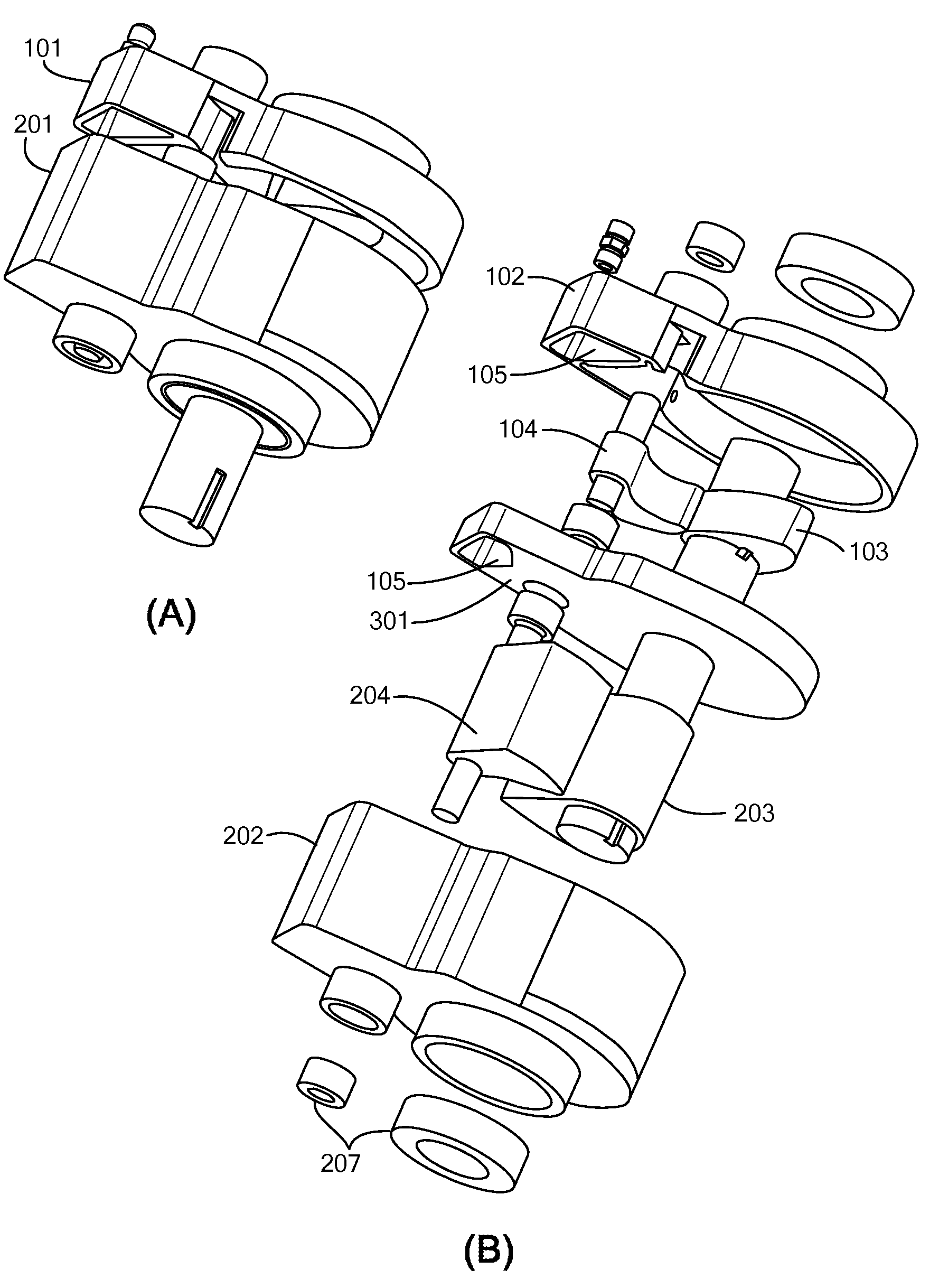
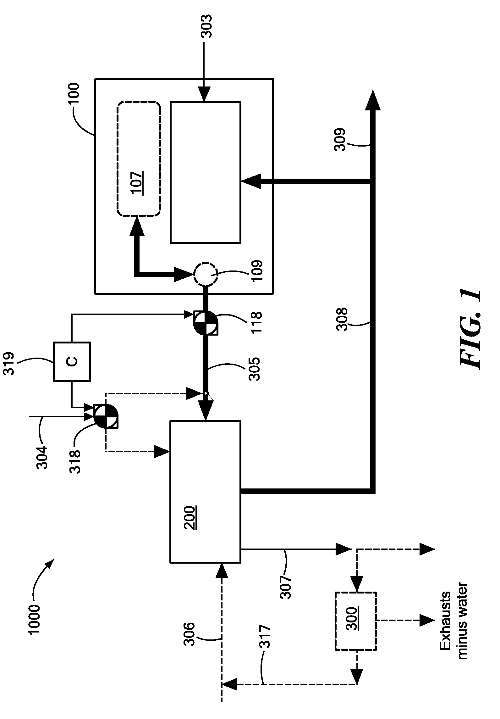
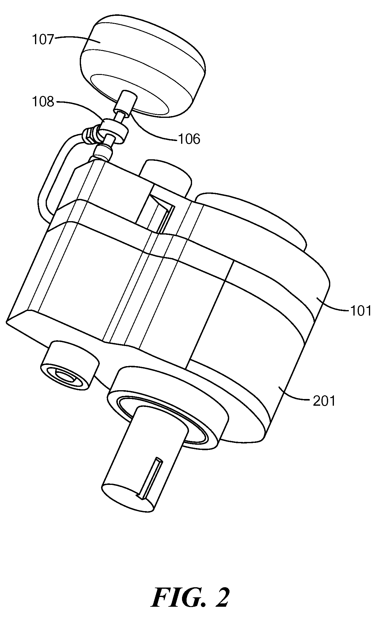
The invention provides an engine that includes a source of pressurized working medium, an expander, a piston, an intake port, an exhaust port, a septum, and a heat input. The engine operates by causing the piston to perform a cycle of movement, which causes the working medium to enter and exit the housing. The intake port allows the working medium to enter the housing, and the exhaust port allows it to exit. The septum is movable with respect to the piston to create a working chamber that is isolated from the intake and exhaust ports. The heat input provides energy to the working medium, and the engine can operate at different duty cycles to provide cooling. The engine can also be a modified axial vane rotary engine or a reciprocating blade engine.

Problems solved by technology

While offering some advantages over existing engines, they too, however, fall short in providing high maximal efficiency.
In addition, HCCI cycle engines also are polluting (particulate matter) and are difficult and costly to control because the ignition event is spontaneous and function of great many variables such as pressure, temperature, exhaust gas concentration, water vapor content, etc.

Method used


Image

  • Hybrid cycle rotary engine
  • Hybrid cycle rotary engine
  • Hybrid cycle rotary engine

Examples


Embodiment Construction

[0053]Definitions. As used in this description and the accompanying claims, the following terms shall have the meanings indicated, unless the context otherwise requires:

[0054]“Sealing contact” of two members shall mean that the members have sufficient proximity directly, or via one or more sealing components, so as to have acceptably small leakage between the two members. A sealing contact can be intermittent when the members are not always proximate to one another.

[0055]A port is “coupled” to a chamber when at least some of the time during a cycle it is in communication with the chamber.

[0056]A full “reciprocation cycle” of a rocker that reciprocates between seated position and a maximum unseated position includes 360 degrees of travel of the main shaft, wherein travel from one of such positions to the other of such positions amounts to 180 degrees of travel of the main shaft.

[0057]The “working medium” describes the various substances which may usefully injected into the working ch...


PUM


Abstract

An internal combustion engine includes in one aspect a source of a pressurized working medium and an expander. The expander has a housing and a piston, movably mounted within and with respect to the housing, to perform one of rotation and reciprocation, each complete rotation or reciprocation defining at least a part of a cycle of the engine. The expander also includes a septum, mounted within the housing and movable with respect to the housing and the piston so as to define in conjunction therewith, over first and second angular ranges of the cycle, a working chamber that is isolated from an intake port and an exhaust port. Combustion occurs at least over the first angular range of the cycle to provide heat to the working medium and so as to increase its pressure. The working chamber over a second angular range of the cycle expands in volume while the piston receives, from the working medium as a result of its increased pressure, a force relative to the housing that causes motion of the piston relative to the housing.

Description

[0001]This application claims priority from U.S. Provisional Patent Application 60 / 834,919, filed Aug. 2, 2006, and U.S. Provisional Patent Application 60 / 900,182, filed Feb. 8, 2007, the contents of which are incorporated herein by reference.FIELD OF THE INVENTION[0002]The present invention relates to engines, and specifically, to hybrid cycle rotary engines.BACKGROUND ART[0003]Excluding very large ship diesels, the typical maximum efficiency of modern internal combustion engines (ICE) is only about 30-35%. Because this efficiency is only attainable in a narrow band of loads (normally close to full load) and because most vehicles typically operate at partial load around 70% to 90% of the times, it should not be surprising that overall, or “well to wheel,” efficiency is only 12.6% for city driving and 20.2% for highway driving for typical mid-size vehicle.[0004]There is prior art in which a Homogeneous Charge Compression Ignition (HCCI) cycle offers to improve the efficiency of inte...

Claims


Application Information

Patent Timeline
Patent Type & Authority Patents(United States)
IPC IPC(8): F02B53/00F01C1/00F04C18/00F04C2/00F02B53/04
CPCF01C11/008F02D41/1479F02B53/04Y10S261/74F02B53/10F02B55/02F02B55/08F02F11/007
Inventor SHKOLNIK, ALEXANDER C.SHKOLNIK, NIKOLAY
Owner LIQUIDPISTON INC
Learn More