
High-speed plug connector with a mounting bracket holding terminals

a high-speed plug and mounting bracket technology, applied in the direction of coupling device connection, electrical discharge lamp, coupling device details, etc., can solve the problems of not meeting the usb 2.0 protocol cannot meet the current transmission speed requirement of new electronic devices, and the difficulty of manufacturing a usb 3.0 connector, etc., to achieve the effect of reducing the mounting surface area

Active Publication Date: 2011-03-22
ADVANCED CONNECTEK INC
View PDF10 Cites 58 Cited by
  • Summary
  • Abstract
  • Description
  • Claims
  • Application Information

AI Technical Summary

Benefits of technology

[0007]The main objective of the invention is to provide a high-speed plug connector that appropriately arranges soldering sections of terminals thereof to effectively reduce mounting surface areas of a printed circuit board (PCB) on which the soldering sections are soldered.
[0008]A high-speed plug connector in accordance with the present invention has an insulating housing, a mounting bracket, multiple first terminals, multiple second terminals and a shell. The first terminals are mounted on the insulating housing. The second terminals are mounted on the mounting bracket. Each terminal has a mounting section, a soldering section and a contacting section. The soldering sections are arranged in a transverse row instead of two rows to make the high-speed plug connector compact and reduce mounting surface areas of a PCB on which the soldering sections is soldered.

Problems solved by technology

However, USB 2.0 protocol only allows a maximum transmission speed of 480 Mbps.
Because electronic devices are constantly developed to increase transmission speeds, the USB 2.0 protocol does not meet current transmission speed requirement of new electronic devices.
However, a USB 3.0 connector having two rows of terminals is structurally complicated so that manufacturing a USB 3.0 connector is difficult.
Furthermore, the terminals of the USB 3.0 connector generate crosstalk and interfere with each other when transmitting high frequency signals.
Therefore, the USB 3.0 connector has a low production rate and a high manufacturing cost.

Method used


Image

  • High-speed plug connector with a mounting bracket holding terminals
  • High-speed plug connector with a mounting bracket holding terminals
  • High-speed plug connector with a mounting bracket holding terminals

Examples


first embodiment

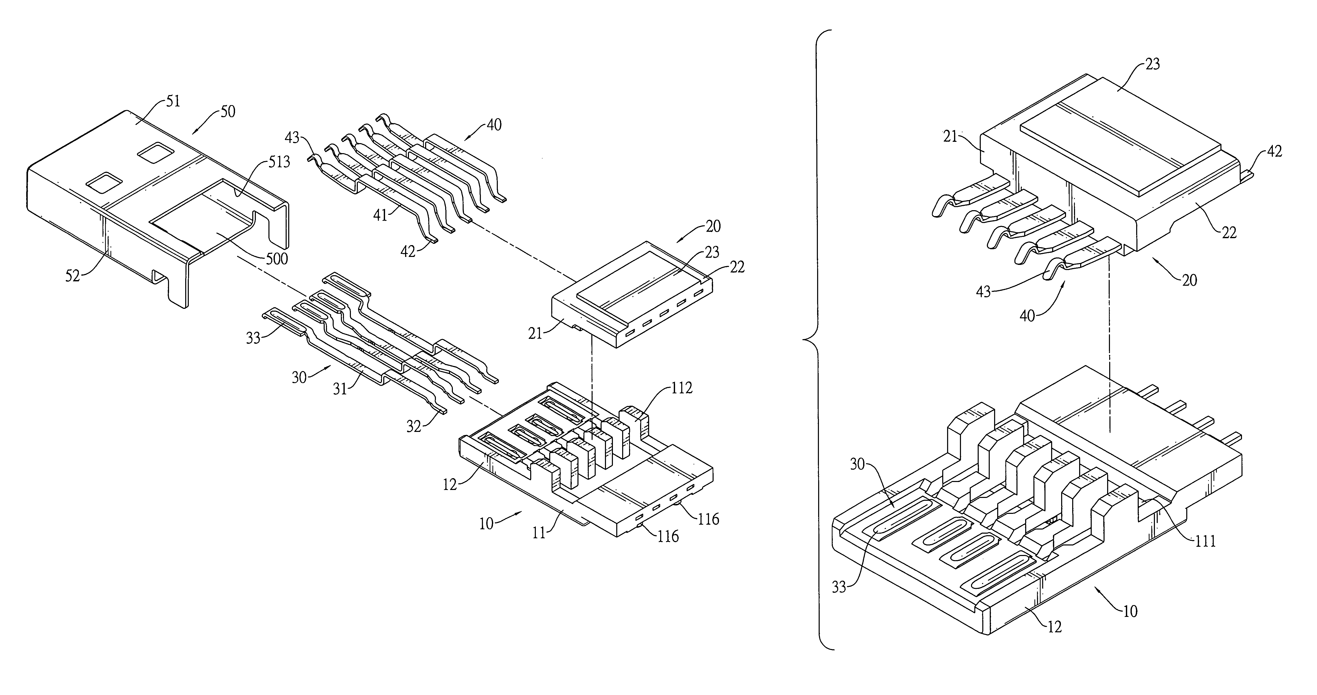
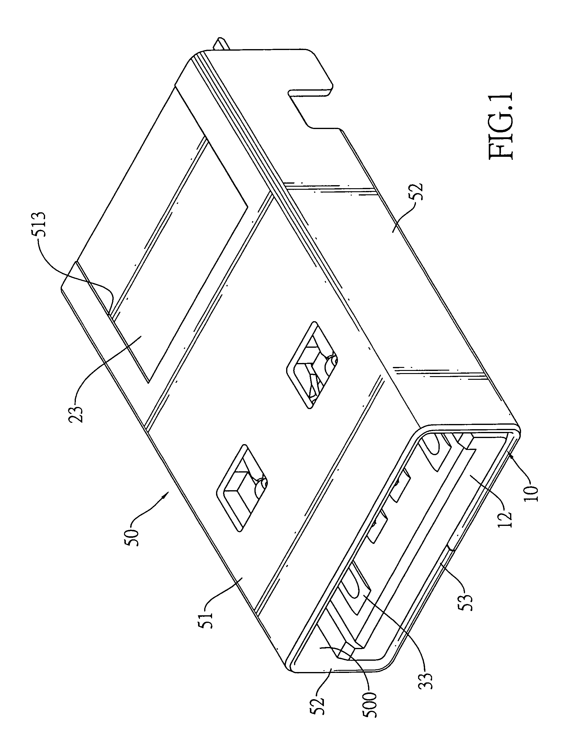
[0020]With reference to FIGS. 1 to 4, a high-speed plug connector accordance with the present invention may comply with type-A USB 3.0 plug connector standards and may be mounted on one end of a cable or in a portable device such as a flash memory storage device.

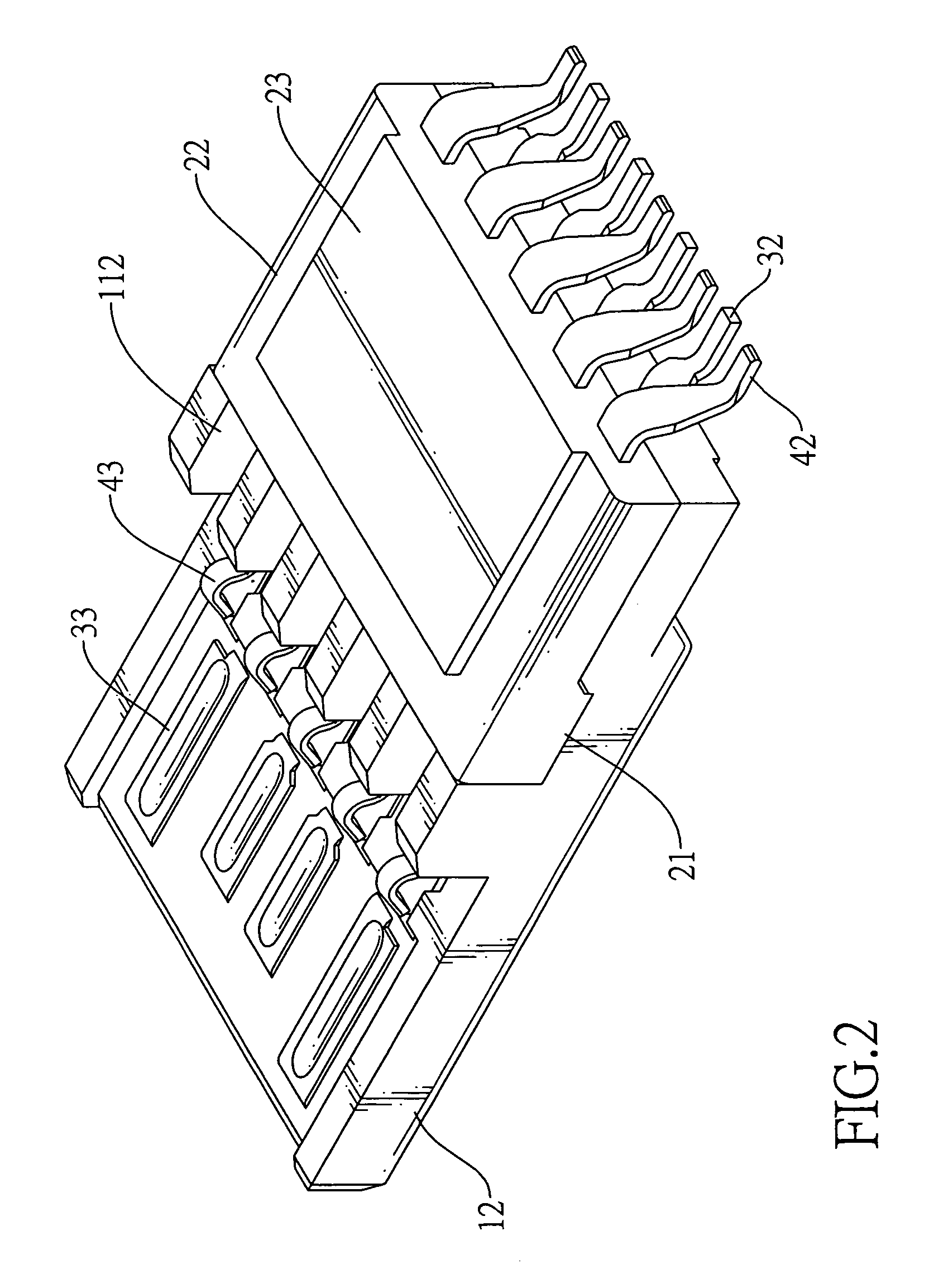
[0021]The high-speed plug connector of the first embodiment is a surface mount technology (SMT) type high-speed plug connector and comprises an insulating housing (10), a mounting bracket (20), multiple first terminals (30), multiple second terminals (40) and a shell (50).

[0022]With further reference to FIG. 5, the insulating housing (10) has a front end, a rear end, a base (11) and a tongue (12).

[0023]The base (11) has a front end, a rear end, a top and a bottom and may further have a fastening slot (111), multiple positioning grooves (112) and multiple assembling protrusions (116). The fastening slot (111) is defined in the base (11). The positioning grooves (112) are defined in the top of the base (11). The assembling pro...

second embodiment

[0049]With reference to FIG. 6B, the high-speed plug connector is a through hole technology (THE) type high-speed plug connector. Therefore, the soldering sections (32a, 42a) of the first and second terminals (30a, 40a) are THE type soldering sections and are straight.

[0050]With further reference to FIG. 8A, a diagram of impedance against time shows a curve indicating impedance of the SMT type high-speed plug connector of the first embodiment during signal transmission. The unit of the impedance is “ohm” and that of the time is “10−12 second (Pico-second, ps)”. As indicated by the curve, when signal transmission is implemented, maximum and minimum impedance values of the SMT type high-speed plug connector are 101.7 and 81.25 ohm and are within a limitation from 75 to 105 ohms of a standard USB 3.0 plug connector. Therefore, advantages of the SMT type high-speed plug connector include high frequency signal transmission.

[0051]With further reference to FIG. 8B, a diagram of impedance a...


PUM


Abstract

A high-speed plug connector has an insulating housing, a mounting bracket, multiple first terminals, multiple second terminals and a shell. The first terminals are mounted on the insulating housing. The second terminals are mounted on the mounting bracket. Each terminal has a mounting section, a soldering section and a contacting section. The soldering sections are arranged in a transverse row instead of two rows to make the high-speed plug connector compact and reduce mounting surface areas of a PCB on which the soldering sections is soldered.

Description

BACKGROUND OF THE INVENTION[0001]1. Field of the Invention[0002]The present invention relates to a connector, and more particularly to a high-speed plug connector that appropriately arranges soldering sections of terminals thereof to effectively reduce mounting surface areas of a printed circuit board (PCB) on which the soldering sections are soldered.[0003]2. Description of Related Art[0004]Conventional Universal Serial Bus (USB) 2.0 connectors are popularly used in various electronic devices. However, USB 2.0 protocol only allows a maximum transmission speed of 480 Mbps. Because electronic devices are constantly developed to increase transmission speeds, the USB 2.0 protocol does not meet current transmission speed requirement of new electronic devices. Therefore, the USB Implementers Forum (USB IF) established USB 3.0 protocol, with a theoretical maximum transmission speed of 5 Gbps.[0005]However, a USB 3.0 connector having two rows of terminals is structurally complicated so tha...

Claims


Application Information

Patent Timeline
IPC IPC(8): H01R24/00
CPCH01R13/514H01R12/712H01R13/6471
Inventor WAN, WEIDUAN, SHU-LINCHEN, CHING-TIENHOU, PIN-YUANKO, WEN-CHIH
Owner ADVANCED CONNECTEK INC
Features
  • Generate Ideas
  • Intellectual Property
  • Life Sciences
  • Materials
  • Tech Scout
  • Unparalleled Data Quality
  • Higher Quality Content
  • 60% Fewer Hallucinations
Learn More