Resistor triggered electrostatic discharge protection

a resistor and electrostatic discharge technology, applied in the direction of diodes, transistors, electrical apparatuses, etc., can solve the problems of modern electronic devices, especially semiconductor devices and integrated circuits (ics), at risk of damag

Active Publication Date: 2011-03-22
NXP USA INC
View PDF14 Cites 12 Cited by
  • Summary
  • Abstract
  • Description
  • Claims
  • Application Information

AI Technical Summary

Problems solved by technology

Modern electronic devices, especially semiconductor (SC) devices and integrated circuits (ICs) are at risk of damage due to electrostatic discharge (ESD) events.

Method used


Image

  • Resistor triggered electrostatic discharge protection
  • Resistor triggered electrostatic discharge protection
  • Resistor triggered electrostatic discharge protection

Examples


first embodiment

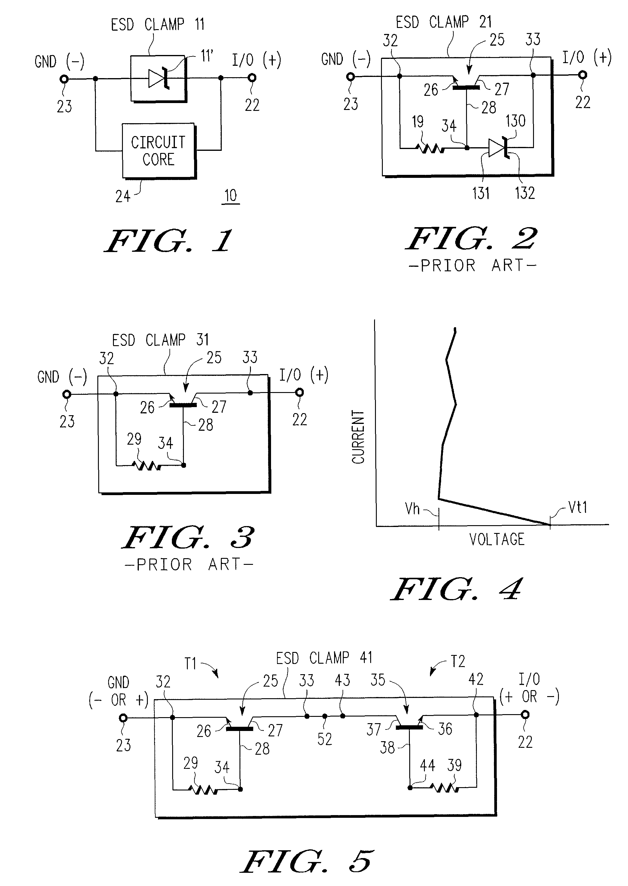
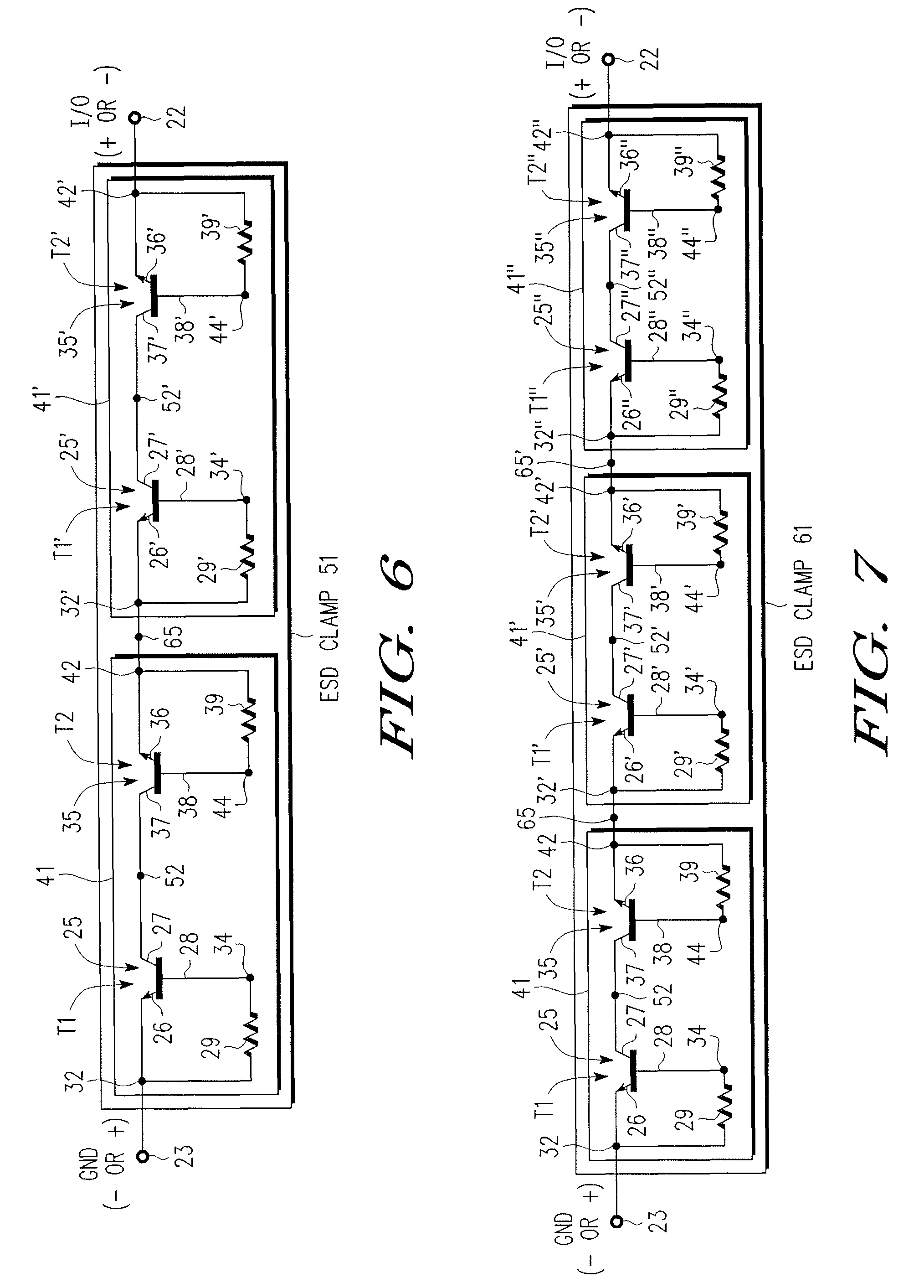
[0032] there is provided an electronic device having input / output (I / O) and common terminals, comprising, a circuit core coupled between the I / O and common terminals, and one or more serially arranged resistor triggered bi-directional ESD clamp stages coupled between the I / O and common terminals. According to a further embodiment, there is only one resistor triggered bi-directional ESD clamp stage. According to a still further embodiment, each resistor triggered bi-directional ESD clamp stage comprises first and second serially coupled bipolar transistors, each bipolar transistor having an emitter, a base and a collector, and wherein the emitter of the first transistor is coupled to the common terminal and the emitter of the second transistor is coupled to the I / O terminals and the collectors of the first and second transistors are coupled together, and a first external resistor is coupled between the emitter and base of the first transistor and a second external resistor is coupled...

second embodiment

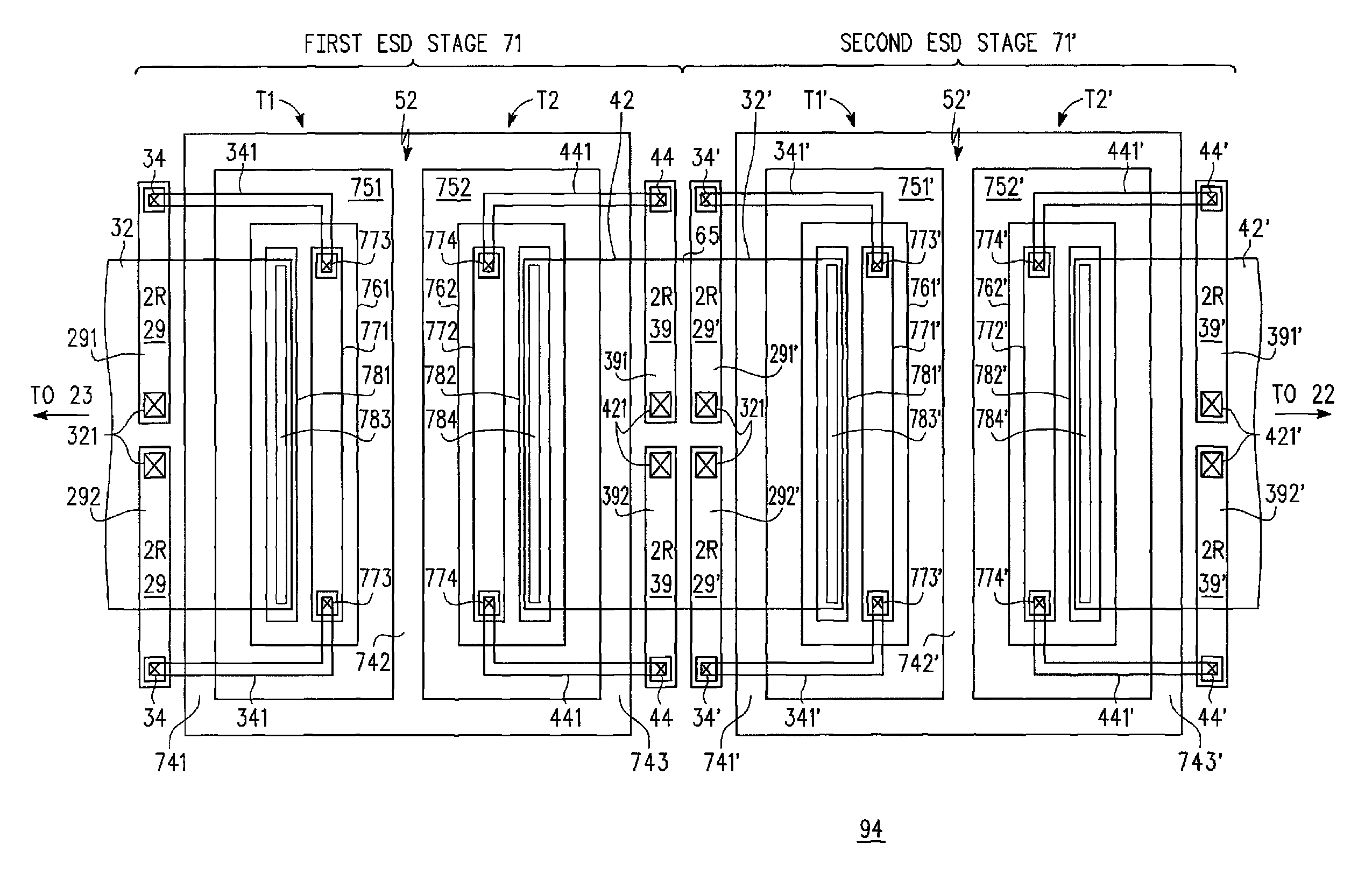
[0033] there is provided an integrated ESD protection device, having I / O and common terminals adapted to be coupled to I / O and common terminals of a core circuit being protected by the integrated ESD protection device, comprising, first and second bipolar transistors having a common collector region and comprising, first and second base regions of a first conductivity type, one base region for each bipolar transistor, a region of a second, opposite conductivity type extending beneath the first and second base regions, and separating and laterally surrounding the first and second base regions, and serving as the common collector region of the first and second bipolar transistors, a first emitter region of the second conductivity type within the first base region and a second emitter region of the second conductivity type within the second base region, wherein the first emitter region is adapted to be coupled to the common terminal of the core circuit and the second emitter region is ...

third embodiment

[0034] there is provided an ESD protection device adapted to be coupled between common and I / O terminals of a core circuit desired to be protected, comprising, one or more bi-directional resistor triggered ESD stages, each stage comprising, two bipolar transistors having a common collector and isolation region, a base region for each transistor separated by a portion of the common collector and isolation region, separate emitter regions, one in each base region, base contact regions, one for each base region, and ESD trigger resistors external to the transistors, coupled between the emitter region and the base contact region of each transistor. According to a still further embodiment, the ESD trigger resistors lie laterally outside the collector and isolation region. According to a still further embodiment, the ESD trigger resistors are thin film resistors. According to a yet further embodiment, the ESD trigger resistors have resistance values in the range of about 0.5 k Ohms to 150...


PUM


Abstract

An electrostatic discharge (ESD) protection device (41, 51, 61, 71, 81) coupled across input-output (I / O) (22) and common (23) terminals of a core circuit (24) that it is intended to protect from ESD events, comprises, one or more serially coupled resistor triggered ESD clamp stages (41, 41′, 41″; 71, 71′, 71″), each stage (41, 41′, 41″; 71, 71′, 71″) comprising first (T1, T1′, T1″, etc.) and second transistors (T2, T2′, T2′″ etc.) having a common collector (52, 52′, 52″) and first (26, 26′, 26″) and second (36, 36′, 36″) emitters providing terminals (32, 42; 32′, 42′; 32″, 42″) of each clamp stage (41, 41′, 41″; 71, 71′, 71. A first emitter (25) of the first stage (41, 71) couples to the common terminal (23) and a second emitter (42″) of the last stage (41″, 71′) couples to the I / O terminals (22). Zener diode triggers are not used. Integrated external ESD trigger resistors (29, 29′, 29″; 39, 39′, 39″) (e.g., of poly SC) are coupled between the base (28, 28′, 28″; 38, 38′, 38″) and emitter (26, 26′, 26″; 36, 36′, 36″) of each transistor (T1, T1′, T1″; T2, T2′, T2″). Different resistor values (e.g., ˜0.5 k to 150 k Ohms) give different ESD trigger voltages. Cascading the clamp stages (41, 41′, 41″; 71, 71′) gives even higher trigger voltages. The ESD trigger resistances (29, 29′, 29″; 39, 39′, 39″) are desirably located outside the common collector-isolation wall (741, 742, 743; 741′, 742′, 743″) surrounding the transistors (T1, T1′, T1″; T2, T2′, T2″).

Description

FIELD OF THE INVENTION[0001]The present invention generally relates to electrostatic discharge (ESD) protection of electronic elements and, more particularly, ESD protection of semiconductor components and integrated circuits.BACKGROUND OF THE INVENTION[0002]Modern electronic devices, especially semiconductor (SC) devices and integrated circuits (ICs) are at risk of damage due to electrostatic discharge (ESD) events. It is well known that electrostatic discharge from handling SC devices and ICs, by humans or machines or both, is a source of such excess voltage. Accordingly, it is commonplace to provide an ESD clamp (voltage limiting device) across the input / output (I / O) and other terminals of such SC devices and IC's. FIG. 1 is a simplified schematic diagram of circuit 10 wherein ESD clamp 11 is placed between input / output (I / O) terminals 22 and ground or common terminal 23 of a SC device or IC to protect the other devices on the chip, that is, to protect circuit core 24 which is al...

Claims


Application Information

Patent Timeline
Patent Type & Authority Patents(United States)
IPC IPC(8): H02H9/00
CPCH01L27/0262H01L29/86H01L29/87
Inventor ZHAN, ROUYINGGILL, CHAI EAN E.WHITFIELD, JAMES D.XU, HONGZHONG
Owner NXP USA INC
Why Eureka
Try Eureka