Solar sail launch system and solar sail attitude control system

a technology of solar sails and launch systems, applied in the direction of spacecraft, transportation and packaging, spacecraft, etc., can solve the problems of inability to allow equipment as light and cheap, inability to control, and inability to operate as easily and efficiently as possible, so as to achieve better steering/attitude control

Active Publication Date: 2011-03-29
ELLINGHAUS FR WERNER
View PDF11 Cites 16 Cited by
  • Summary
  • Abstract
  • Description
  • Claims
  • Application Information

AI Technical Summary

Benefits of technology

[0022]Also is the existing basic roller-reefing design improved against material fatigue of the steering foils which have to be furled and unfurled often and also for better steering / attitude control, which is an additional aim of this present application.

Problems solved by technology

Because robot and astronaut labor in space is extremely limited and costly, out of this circle of experts came the proposal to develop a solar sail based on the previous designs which does not has to be mounted in space.
Such preferred Near-Sun mining missions to asteroids would presumably be orders of magnitude more cost effective than similar missions to the Moon, as those would have to be completed in much higher gravity conditions with a lot less Sun-energy available hence not allowing equipment that is as light and cheap.
Control is further complicated by gravitational forces as those of Earth, which have to be factored in also.
Unwanted torsion forces from shifted force centers arise on other space crafts also and are called “thrust vector misalignment problem”.
Without counter measures this would lead to a solar sail turning away from the best possible orientation to the Sun.
In the worst case it could neither be steered in a sufficient manner nor driven into the direction desired.
However, vane steering has it's disadvantages too.
In abnormal steering situations it could happen, that vanes don't work, such as when Sun pressure is parallel to the sail foils of the solar sail and of the vanes as well.
On self-deploying square solar sails with self-expanding masts, complications can be expected.
A disadvantage of steering a solar sail by roller reefing and unfurling is expected fatigue of the thin sail foil material.
The problem however is material fatigue due to frequently rolling the foil on and off which would damage the sail after some time.
This problem shall be solved for the steering part but unfortunately not for the part of frequent sail setting and reefing.
This method has a drawback as well, which would still be acceptable.
A part of the possible sail area is lost due to the shortened sail foil length.
Because of this the mechanical properties steering / ACS would become over-complicated making it handicapped or nearly impossible.
Problems: Though direct construction of a solar sail and even production of parts in space would be certainly optimal (for instance production of sail foils) the current robotic technique has not evolved sufficiently for those tasks or the needed development would be extremely expensive and long-winded.
The reason for this need is, that the orbit speed of the solar sail (for instance near the ISS) with it's large sail area would get slowed down through atmospheric particles so much that crash down would be unavoidable.
Another problem of self deflating solar sails is that the sail foils have to be folded before launch and unfolded again when it has reached the place of action.
At first the risk of failure is pretty high for unfolding solar sail foils.
Additionally the sail foils would crease and could get damaged through this.
Out of this reason the sail foils thickness has to be selected accordingly, which leads to an unnecessary mass enhancement.
However this design of the last application relates to very large space constructed systems with stiff carrying Outer Ring which is assembled from pipe segments.
This would shorten the duration of the mission substantially.
That saves unnecessary mass at the solar sail.
Admittedly the sailcraft has one serious disadvantage.
The mass / thrust-relation especially when using aluminum as structural material, is very poor.
In contrast to this, known designs of self unfolding solar sails feature sparse payload volume, no solar cell arrays and certainly no docking station for daughter units.
Admittedly those advantages are restricted through the disadvantage of the self deploying solar sail's much higher mass.

Method used


Image

  • Solar sail launch system and solar sail attitude control system
  • Solar sail launch system and solar sail attitude control system
  • Solar sail launch system and solar sail attitude control system

Examples


Embodiment Construction

Integrated Prior Art

[0035]As it is the scope of this invention to implement essential parts of the inventors prior art previously thought for large space mounted spacecraft into a direct launch able solar sail spacecraft, those prior art items, which are also applied to this application, shall be explained underneath. However the inventor emphasizes, that special adaptations have been designed, which allow to integrate ALL of those features together into one single spacecraft AND deploys in space.

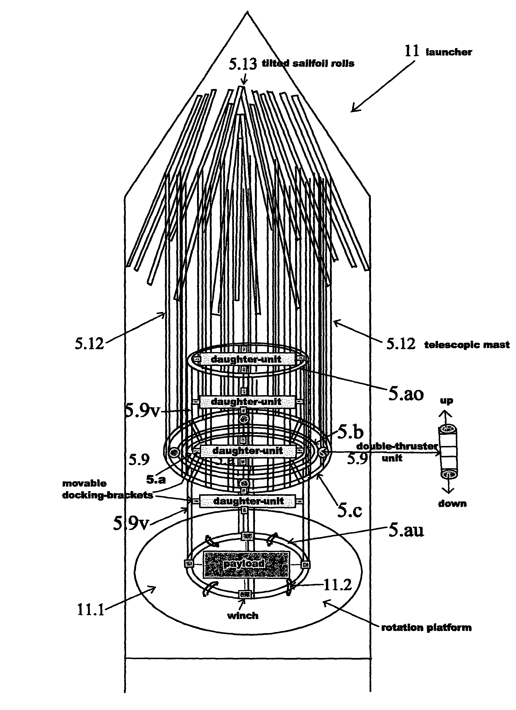
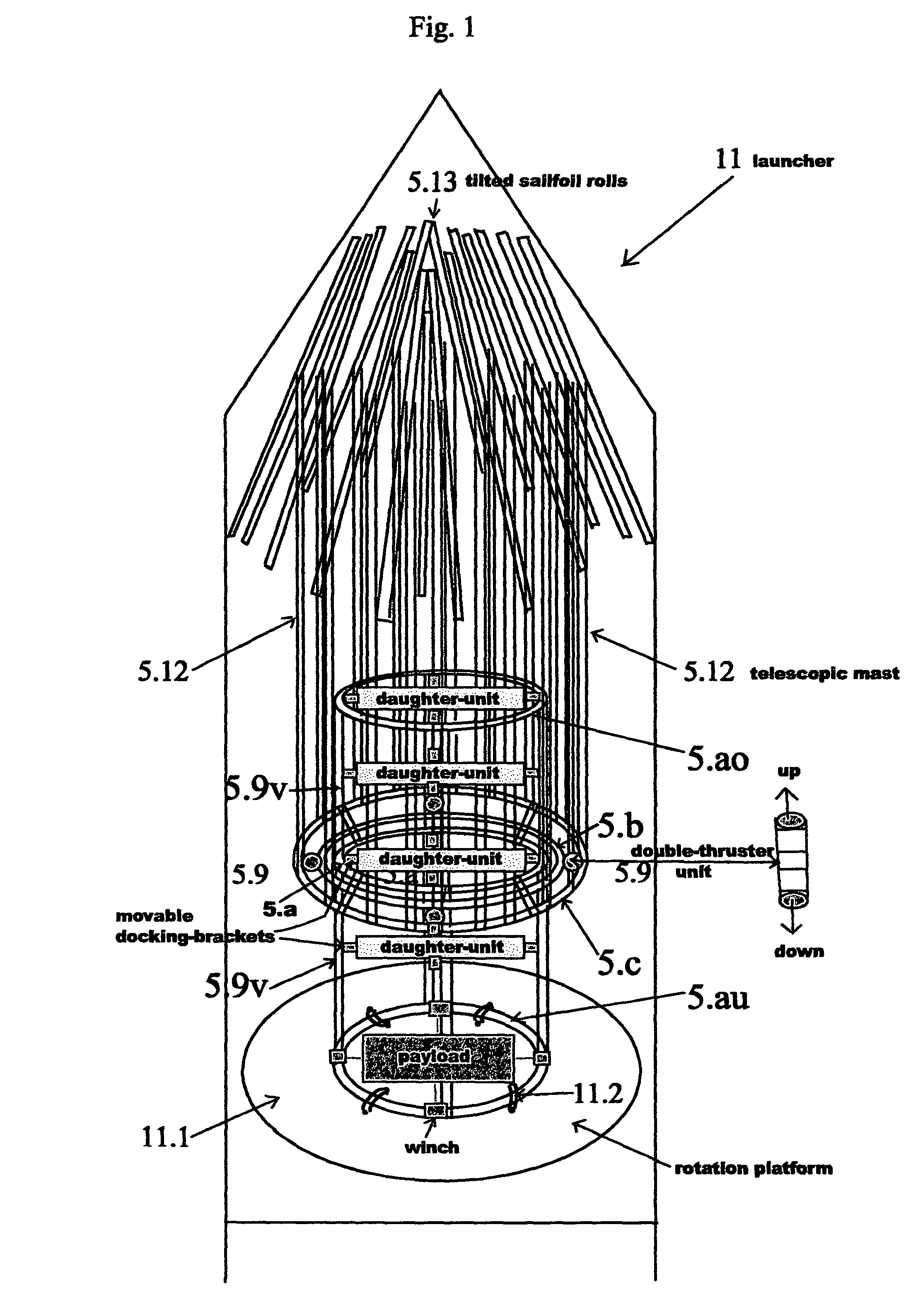
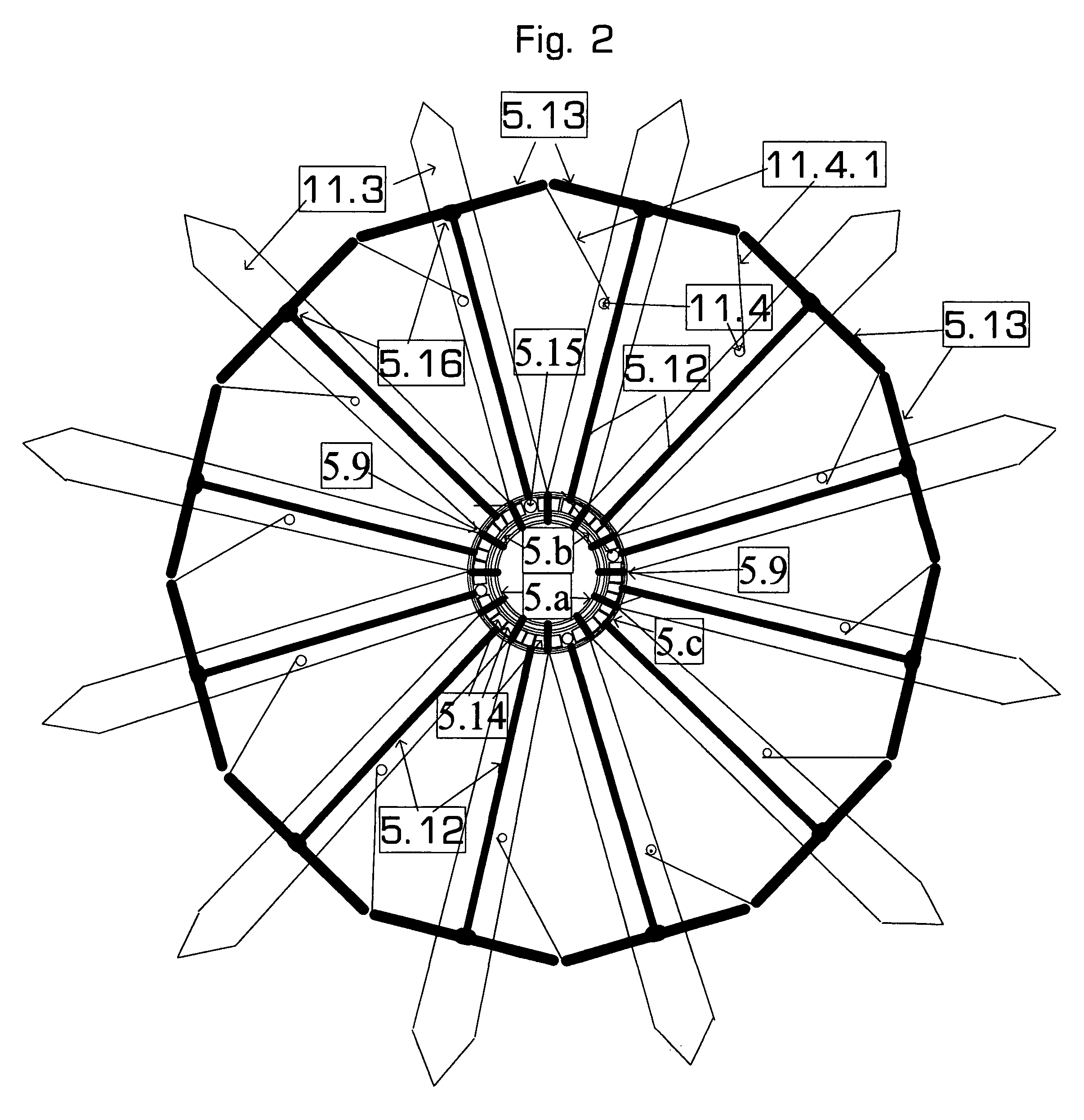
[0036]Docking- and Payload-Station—German patent appl. DE 10 2004 004 543 consisting of one or more Inner Rings which are connected among one another and stretched or hang into the center of the Solar Sail spacecraft.

[0037]To dock several daughter units and payload, movable docking brackets and winches are attached to the station, which allow to take in and hold daughter unit spacecraft and payload.

Inner-Ring-Construction (DE 10 2005 028 3780)

[0038]The Inner-Ring-Construction for Thruster-S...


PUM


Abstract

Fuel less ACS for solar sails, using furl- and unfurl able ballast-sail-foil-segments for simultaneously displacement of center of mass and center of solar radiation pressure into opposite directions to each other.Solar-Sail-Launch-System for direct launch of the System-Sail including already docked in daughter units and payload in the sailcraft's central docking station.Unlike todays launch able solar sail designs the System-Sail features ample solar cell arrays and additional SEP-thruster-units for steering and propulsion, while the solar sail rather serves for longtime fuel less attitude controls and station keeping.The SEP-Sailcraft may also serve as a carrier-ship for daughter-units in asteroid exploration missions and is able to deliver prospector landers back to LEO with furled in foils.

Description

REFERENCE TO RELATED APPLICATIONSPriority Claim[0001]This application is based upon and claims the benefit of priority of the co-pending German Patent Application No. 10 2005 062 841.9, filed on Dec. 28, 2005. The disclosure of which is expressly incorporated by reference herein.Related Applications of the Inventor[0002]DE 102 34 902 B4, DE 102 004 004 543 A1, DE 10 2005 028 3780. This actual patent application has also been filed in the U.K. and became patented under GB 2434 345 B and under DE 10 2005 028 378 in. Germany.Other Related Applications[0003]U.S. Pat. No. 4,426,052 A, US 20020116877 A1, US 2006 / 001783, US 2005 / 0274849, US 2005 / 0103940, U.S. Pat. No. 5,299,764, EP 1280228 A2, EP 0524888 A1, WO 1990 / 006259 A1, RU 002101811C1, RU 002053941 C1.Related Papers[0004]Pryor, Wie et al., “Development of a Lightweight Pulsed Plasma Thruster Module for Solar Sail Attitude Control”, 18. Annual AIAA / USU Conference on Small Satellites.[0005]Wie, Murphy at al. “Robust Attitude Control S...

Claims


Application Information

Patent Timeline
Patent Type & Authority Patents(United States)
IPC IPC(8): B64C1/10
CPCB64G1/222B64G1/407B64G1/22
Inventor ELLINGHAUS, FRANK WERNER
Owner ELLINGHAUS FR WERNER
Why Eureka
Try Eureka