Single fold device for tissue fixation

a single-fold device and tissue fixation technology, applied in the field of medical equipment and methods, can solve the problems of few, if any, interventional options for patients who are considered obese or moderately obese, and achieve the effects of preventing kinking or pinching of tubes, preventing rotation, and maintaining the stability of the stapler assembly

Active Publication Date: 2011-03-29
ETHICON ENDO SURGERY INC
View PDF453 Cites 1620 Cited by
  • Summary
  • Abstract
  • Description
  • Claims
  • Application Information

AI Technical Summary

Benefits of technology

[0012]One or both of the pod members may additionally define a vacuum chamber or opening into which the tissue may be drawn within. The opening of the vacuum chamber may be slotted along a direction parallel to a longitudinal axis of the working body; alternatively, the opening may be defined a variety of shapes, e.g., oval, elliptical, etc., and furthermore may be offset such that it is defined transverse to the longitudinal axis of the working body. Adjacent to and preferably parallel with the vacuum chamber is a tensioning arm or member, which may have a length equal to that of the vacuum chamber. Alternatively, a length of the tensioning member may be less than or greater than that of vacuum chamber. The distal end of each pod member may have a flexible and / or atraumatic tip such as a blunt, rounded, or “bullet” tip, made from any number of polymers to facilitate the guidance of the pod assembly into the hollow body organ without damaging tissue along the way.
[0014]Vacuum tubes may be routed through the length, or a partial length, of the working body for communication with the pod assembly. The proximal ends of the vacuum tubes may be connected to one or more vacuum pumps. Furthermore, the vacuum tubes may utilize braided materials, e.g., stainless steel or superelastic materials such as Nickel-Titanium alloy, integrated throughout to prevent kinking or pinching of the tubes.
[0015]The fixation assembly comprises, in part, a manipulatable stapler assembly connected via a flexible shaft to a stapler handle. The stapler assembly itself generally comprises a staple cartridge housing within which one or more staples are housed. A corresponding anvil is positioned in apposition to the staple cartridge housing and may be used to provide a staple closure surface when tissue to be affixed is adequately positioned between the staple cartridge housing and the anvil. With the stapler assembly connected at the distal end of a flexible shaft, a handle is connected at the proximal end of the shaft. The handle itself may allow the surgeon or user to hold and manipulate the fixation assembly while articulating the stapler assembly between an open and closed configuration. Moreover, the configuration of the handle allows the surgeon or user to actuate the stapler assembly as well as deploy the staples from the staple cartridge housing.
[0016]In use, the fixation assembly may be advanced within the folder assembly main lumen with the fixation assembly configured in a closed configuration. To maintain an orientation, i.e., rotational stability, of the fixation assembly relative to the folder assembly and the approximated tissue, the fixation assembly may be configured to have a shape which is keyed to a cross-sectional area of the folder assembly main lumen. The keyed configuration helps to ensure that as the fixation assembly is advanced through the folder assembly, that the stapler assembly is optimally positioned to be clamped over the tissue for fixation.
[0017]When the stapler assembly is advanced and has exited the main lumen of the working body, the staple cartridge housing may be actuated into an open configuration when positioned between distally extending arm members of a yoke to receive the tissue folded between the pod members. The yoke arm members are configured such that when the stapler assembly is positioned therebetween, the stapler assembly is prevented from rotating or bending out of alignment for tissue affixation, i.e., the lateral stability of the stapler assembly is maintained relative to the yoke and the tissue. The stapler assembly may then be advanced distally over the folded tissue and clamped onto the tissue for deploying the staples. To avoid damaging tissue surrounding the pod assembly, one or several insertion indicators may be defined along a portion of flexible shaft of the fixation assembly, preferably near a proximal end of the shaft, to aid the user in knowing when the stapler assembly may be safely articulated while the fixation assembly is positioned within the working body, i.e., the longitudinal stability of the stapler assembly is maintained relative to the folder assembly. The indicators may be configured to align with a proximal end of the folder handle to correspondingly indicate, e.g., a position of the fixation assembly relative to the folder assembly when the stapler assembly may be opened, and / or how far distally the fixation assembly may be advanced relative to the folder assembly to engage the folded tissue, and when the devices are in a “safe to clamp” mode (e.g., in position around the tissue). Such positional indicators may utilize mechanical features, such as a stop or detent. In addition, the stapler assembly jaws my be spring-loaded open to assist insertion.

Problems solved by technology

Although the outcome of these stomach reduction surgeries leads to patient weight loss because patients are physically forced to eat less due to the reduced size of their stomach, several limitations exist due to the invasiveness of the procedures, including time, use of general anesthesia, time and pain associated with the healing of the incisions, and other complications attendant to major surgery.
In addition, these procedures are only available to a small segment of the obese population (morbid obesity, Body Mass Index≧40) due to their complications, leaving patients who are considered obese or moderately obese with few, if any, interventional options.
In addition, because of the invasiveness of most of the surgeries used to treat obesity and other gastric disorders such as GERD, and the limited success of others, there remains a need for improved devices and methods for more effective, less invasive hollow organ restriction procedures.

Method used


Image

  • Single fold device for tissue fixation
  • Single fold device for tissue fixation
  • Single fold device for tissue fixation

Examples


Embodiment Construction

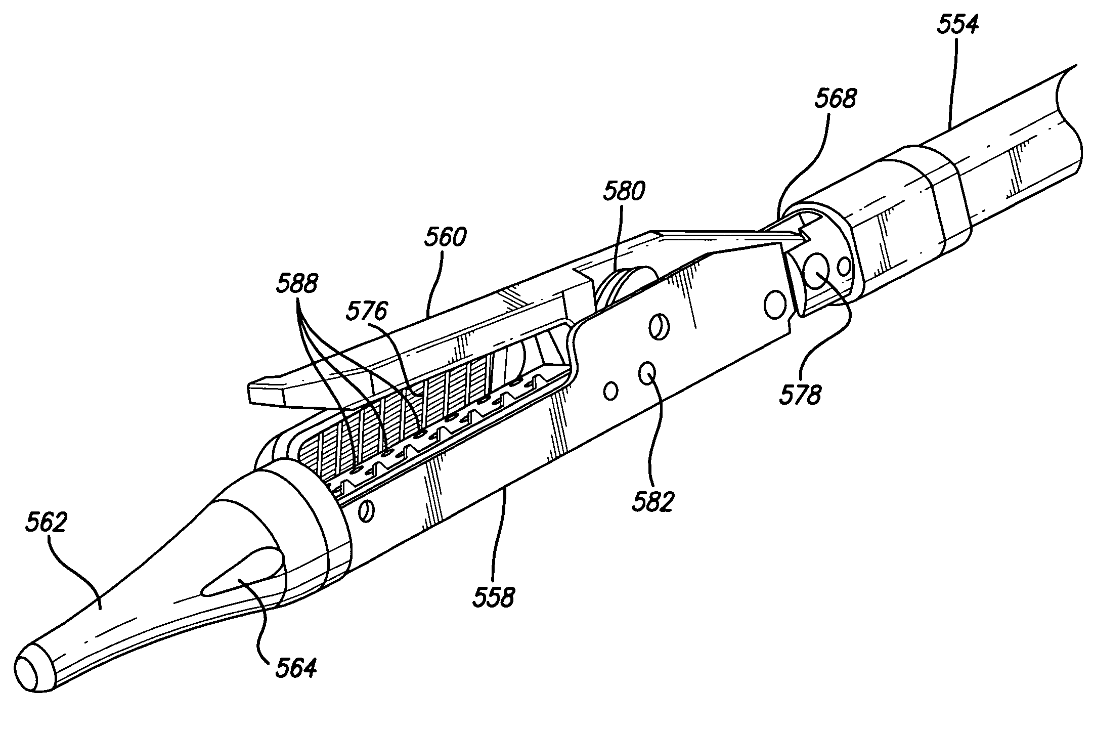
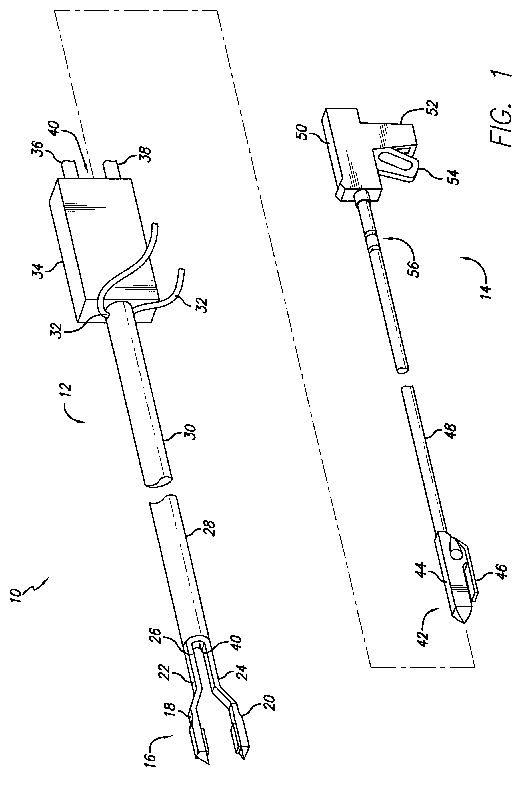
[0093]A system for tissue approximation and fixation is described which may be utilized for approximating tissue regions from within a hollow body organ, such as the stomach, esophageal junction, and other portions of the gastrointestinal tract. The system may be advanced within a body through a variety of methods, e.g., transorally, transanally, endoscopically, percutaneously, etc., to create one or several divisions or plications within the hollow body organ. At least two devices may be utilized as part of the system, a tissue acquisition and folding system and a tissue stapling or fixation system, although it is contemplated that both devices can be integrated into a single mechanism. Each of these devices may be configured to efficiently operate with one another to provide optimal methods and devices for at least acquiring, approximating, and stapling regions of tissue from within the hollow body organ in a minimally invasive manner.

[0094]Turning now to the figures, the system w...


PUM

PropertyMeasurementUnit
volumeaaaaaaaaaa
diameteraaaaaaaaaa
volumeaaaaaaaaaa

Abstract

A system for tissue approximation and fixation is described herein. A device is advanced in a minimally invasive manner within a patient's body to create one or several divisions or plications within a hollow body organ. The system comprises a stapler assembly having a tissue acquisition member and a tissue fixation member. The stapler assembly approximates tissue from within the hollow body organ with the acquisition member and then affixes the approximated tissue with the fixation member. In one method, the system can be used as a secondary procedure to reduce the size of a stoma within the hollow body organ.

Description

CROSS-REFERENCE TO RELATED APPLICATION[0001]This application is a continuation-in-part of application Ser. No. 10 / 686,326 filed on Oct. 14, 2003, now U.S. Pat. No. 7,097,650, which is herein incorporated by reference.BACKGROUND OF THE INVENTION[0002]1. Field of the Invention[0003]The present invention relates generally to medical apparatus and methods. More particularly, it relates to devices and methods for approximating portions of a hollow body organ, particularly a stomach, intestine, or other region of the gastrointestinal tract, while affixing the tissue.[0004]2. General Background and State of the Art[0005]In cases of severe obesity, patients may currently undergo several types of surgery either to tie off or staple portions of the large or small intestine or stomach, and / or to bypass portions of the same to reduce the amount of food desired by the patient, and the amount absorbed by the gastrointestinal tract. The procedures currently available include laparoscopic banding, ...

Claims


Application Information

Patent Timeline
Patent Type & Authority Patents(United States)
IPC IPC(8): A61B17/08A61B17/04A61BA61B17/072A61B17/11A61B17/28A61B17/32
CPCA61B17/07207A61B17/1114A61B17/29A61F5/0083A61B1/3132A61B2017/00278A61B2017/003A61B2017/00323A61B2017/0034A61B2017/00353A61B2017/00946A61B2017/07214A61B2017/1103A61B2017/2905A61B2017/306A61B2019/481A61F5/005A61F5/0076A61B2090/08021A61B2017/00876
Inventor ROTH, ALEX T.HANCOCK, ANDREW H.WELLER, GARYMATA, JR., GILBERTGERBI, CRAIGGANNOE, JAMESJULIAN, CHRISTOPHER
Owner ETHICON ENDO SURGERY INC
Why Eureka
Try Eureka