Side branch stent graft construction

a stent and side branch technology, applied in the field of medical devices, can solve the problems of insufficient length of stent graft and insufficient length for sealing of extension arms, and achieve the effect of reducing the diameter

Active Publication Date: 2011-03-29
COOK MEDICAL TECH LLC
View PDF18 Cites 60 Cited by
  • Summary
  • Abstract
  • Description
  • Claims
  • Application Information

AI Technical Summary

Benefits of technology

[0010]It will be seen that by having the tubular side branch mounted into the fenestration and extending in both directions from the fenestration sufficient length for sealing of an extension arm into the tubular side branch is provided without having the tubular side branch extending too far into the stent graft tubular body.
[0012]In a preferred embodiment the tubular body has a tapered portion and the fenestration is in the tapered portion. In the region of the coeliac and superior mesenteric arteries, the aorta tapers as these major branch vessels extend from the aorta and tapering of the stent graft assists with maintaining a good blood flow and pressure in the stent graft.
[0016]The or each ring may be formed from at least two turns and preferably three turns of a shape memory wire such as Nitinol™ wire and the ends of the Nitinol™ wire may terminate in loops. The use of the loops prevent sharp ends from the Nitinol™ wire from digging into the vasculature into which the stent graft is deployed. The rings are stitched to the tube by stitching. The rings can alternatively be formed from stainless steel wire, plastics material or other suitable material. Stitching of the loops on the rings to the biocompatible graft material also prevents the resilient rings from being expanded by the pressure of a self expanding or balloon expandable stent placed therein and expanded.
[0018]In one embodiment the resilient stent defines a cylindrical form having a diameter less than that of the tubular side branch to define a self contracting stent and hence when sewn onto the outside of the tube using stitching it provides a diameter reducing effect on the tubular side branch.
[0019]Also provided on the tubular side branch may be radiopaque markers adjacent each of the ends of the tubular side branch. These markers enable the physician to visualise the tubular side branch during an operation to assist with correct placement of a leg extension into the tubular side branch.
[0022]It will be seen that by having the tubular side branch mounted into the fenestration and extending in both directions from the fenestration sufficient length for sealing of an extension arm into the tubular side branch is provided without having the tubular side branch extending too far into the stent graft tubular body. The linear portion of the inner circumferential end engaging against the wall provides a low profile for the inner end within the tubular body. This also assists with enabling a physician to extend a guide wire into the side arm because a guide wire being directed down along the inner wall of the tubular body will more easily enter the side branch where the circumference extends around and along the wall for some distance.

Problems solved by technology

In some regions of the aorta such as the thoracic arch and the infra renal region there is often insufficient length of stent graft proximally of the fenestration to allow an internal arm of sufficient length to be used.
If the internal arm is made too short then there is insufficient length for sealing of the extension arm.

Method used


Image

  • Side branch stent graft construction
  • Side branch stent graft construction
  • Side branch stent graft construction

Examples


Embodiment Construction

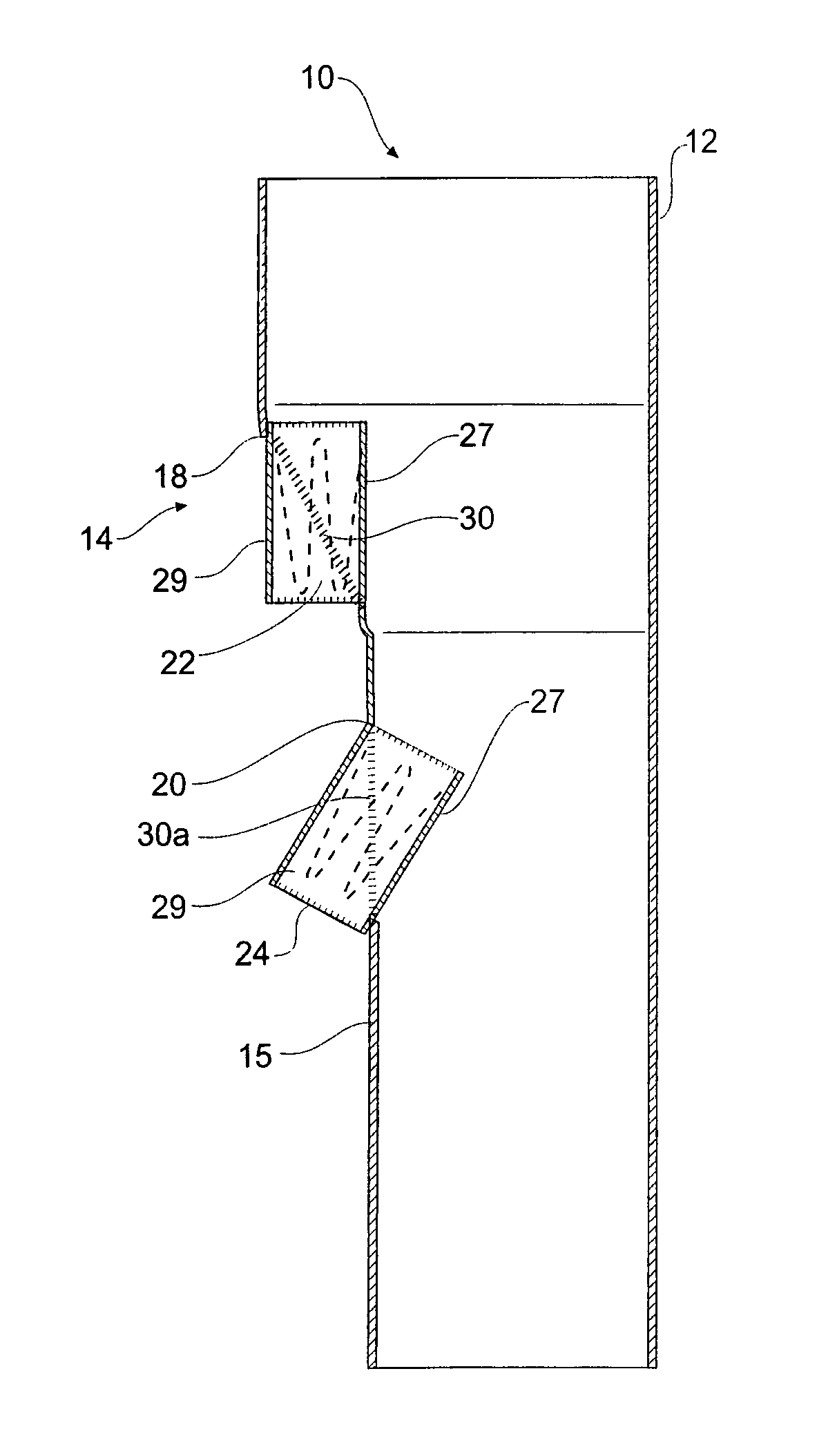
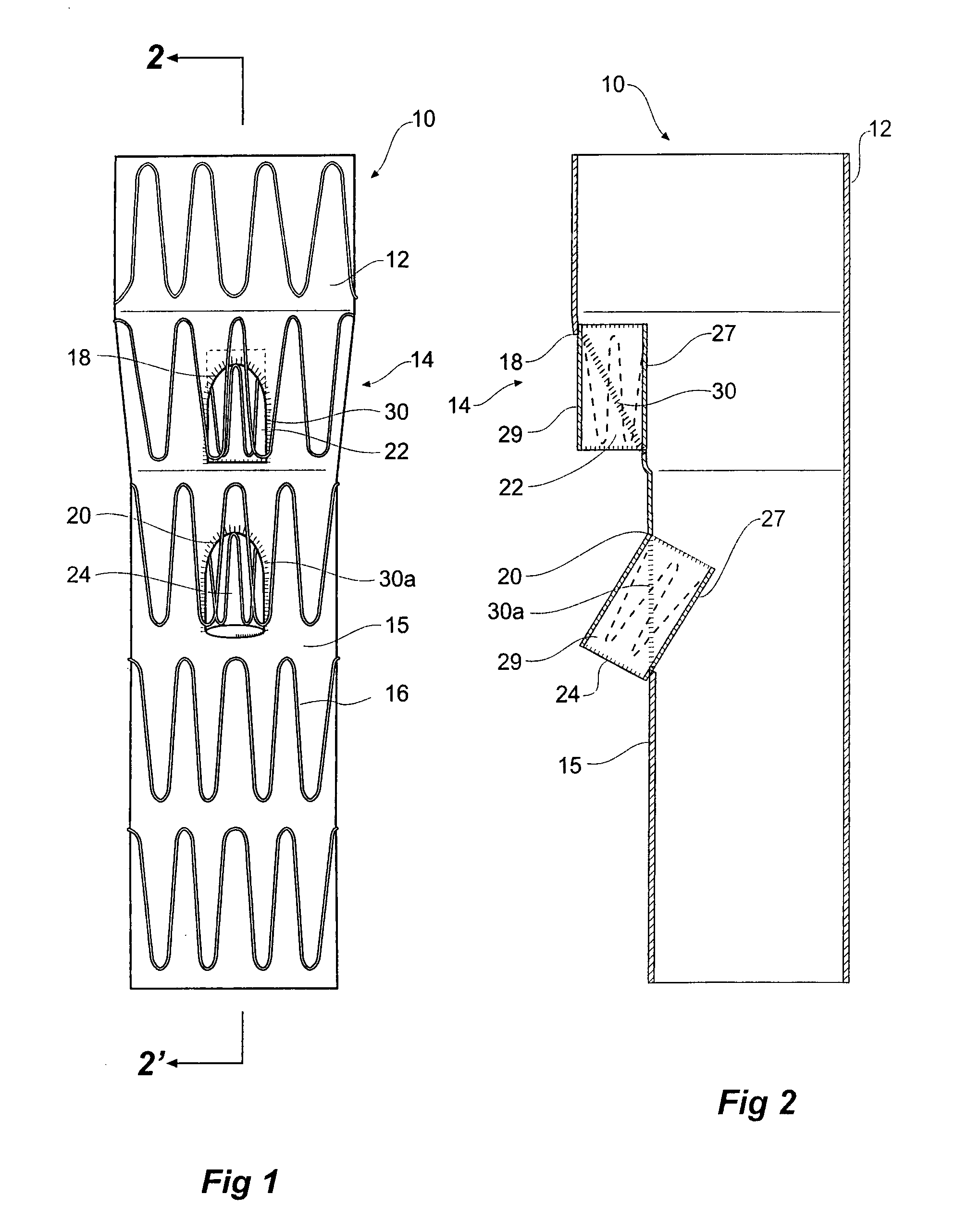
[0043]Looking more closely at the drawings and in particular FIGS. 1 to 2 showing a first embodiment of a stent graft according to the present invention, it will be seen that stent graft 10 has a tubular body 12 which includes a tapered central region 14 and a lower parallel sided portion 15. The tubular body is supported by stents 16. Preferably these stents are self expanding Gianturco zig zag Z stents but other forms of stents may also be included.

[0044]In the tapered region 14, there is a fenestration 18 and in the lower parallel sided portion 15 of the tubular body 12 there is another fenestration 20. Mounted into each of the fenestrations 18 and 20 are tubular side branches 22 and 24 respectively.

[0045]As can be particularly seen in FIG. 2, the tubular side branches 22 and 24 each have an inner portion 27 which extends within the tubular body of the stent graft and an outer portion 29 which extends outside of the tubular body of the stent graft. The tubular side branches are d...


PUM


Abstract

A stent graft (10) has a tubular body (12) of a biocompatible material and at least one fenestration (18, 20). The or each fenestration has a tubular side branch stitched into it with a portion of the tubular side branch extending within the tubular body and a portion of the tubular side branch extending exteriorly of the tubular body. The stitching by which the tubular side branch is mounted into the fenestration extends circumferentially and diagonally from one end of the tubular side branch to the other such that the tubular side branch extends from the tubular body at an angle thereto. The tubular side branch has a resilient ring around at least one and preferably both ends thereof and a self expanding stent in between them. The tubular side branch can have a circumferential linear portion (46) at an inner end to engage against the inner wall (58) of the tubular body. The tubular side branch can have a stent made from a single wire forming a first ring (45), a second ring (47), the second ring defining a plane which is substantially parallel to and spaced axially apart from the plane of the first ring and a number of helical wire portions (49) extending between the first and second ring. Preferably the wire is a shape memory wire such as Nitinol™ wire.

Description

CROSS-REFERENCE TO RELATED APPLICATIONS[0001]This application claims priority of provisional application Ser. No. 60 / 776,423, filed Feb. 23, 2006 and provisional application Ser. No. 60 / 773,240 filed Feb. 13, 2006.TECHNICAL FIELD[0002]This invention relates to a medical device and more particularly to a stent graft for endovascular deploymentBACKGROUND OF THE INVENTION[0003]Stent grafts have been devised for endovascular deployment to bypass a diseased portion of a vessel and such stent grafts can be deployed into body vessels such as the aorta. Where there are branches from the body vessel such as the coeliac artery, the superior mesenteric artery and the renal arteries it is desirable to have a fenestration in the stent graft so that an extension arm can be placed through the fenestration to allow flow into the branch vessel.[0004]In the renal and suprarenal region of aorta, the use of stent graft with fenestrations in the wall of the stent graft provides difficulty for catheteris...

Claims


Application Information

Patent Timeline
Patent Type & Authority Patents(United States)
IPC IPC(8): A61F2/06
CPCA61F2/07A61F2/88A61F2/954A61F2002/061A61F2002/067A61F2/89A61F2002/30327A61F2002/30461A61F2002/9665A61F2220/0075A61F2250/0039A61F2002/075
Inventor HARTLEY, DAVID ERNESTMORRISS, SUSANDUCKE, WERNER D.CHUTER, TIMOTHY A.
Owner COOK MEDICAL TECH LLC
Why Eureka
Try Eureka