Method of synchronizing a turbomachine generator to an electric grid

a technology of turbomachine and electric grid, which is applied in the direction of electric generator control, motor/generator/converter stopper, dynamo-electric converter control, etc., can solve the problems of unsatisfactory transients, and inability to adjust the synchronization process. , to achieve the effect of increasing the voltage value and reducing the time to synchroniz

Active Publication Date: 2011-03-29
GENERAL ELECTRIC CO
View PDF12 Cites 27 Cited by
  • Summary
  • Abstract
  • Description
  • Claims
  • Application Information

AI Technical Summary

Benefits of technology

[0007]In an embodiment of the present invention, a method of reducing the time to synchronize a turbomachine generator with an electrical grid system, the method comprising: determining a voltage value of a 
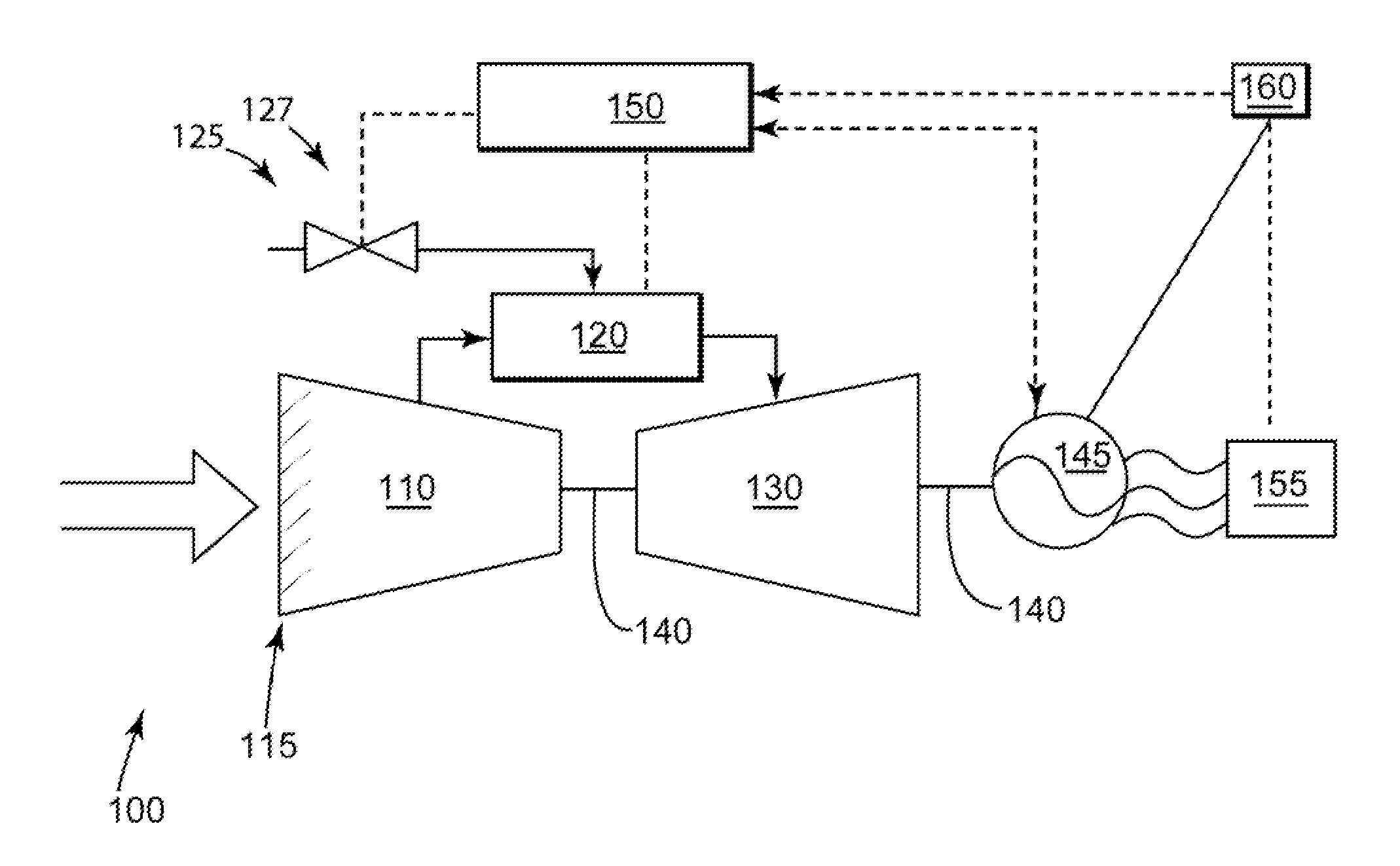
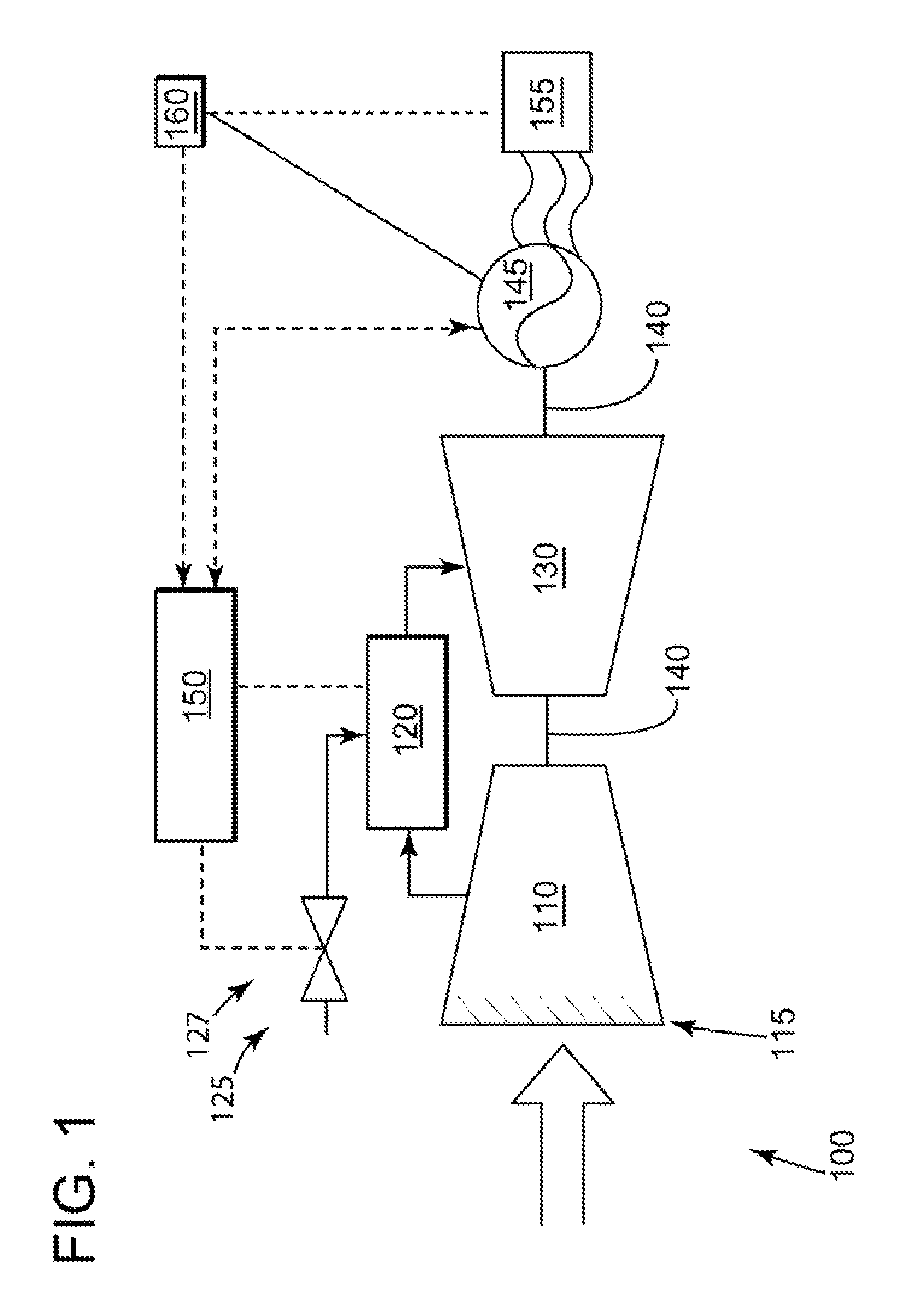
grid system; wherein a generator is integrated with a turbomachine and is configured for exporting electricity to the grid system; and wherein the generator comprises a generator field; applying a target bias to the voltage value; wherein the target bias assists the generator with delivering a positive voltage to the grid system; conditioning the voltage value; wherein the conditioning increases an accuracy of the voltage value; determining a voltage target for the generator, wherein an exciter transforms the voltage value into the voltage target; and conditioning the voltage target to determine if the voltage target is within a preferred range; wherein the method allows the exciter to precondition a generator voltage regulator with the voltage target in preparation for synchronization as the turbomachine is accelerating to a synchronization speed.
[0008]In an alternate embodiment of the present invention, a method of reducing the time to synchronize a turbomachine generator with an electrical grid system, the method comprising: providing a generator integrated with a turbomachine, wherein the generator is configured for exporting electricity to a grid system and comprises a generator field; controlling a speed loop, wherein the speed loop performs the steps of: determining a grid speed, wherein the speed corresponds to a frequency of the grid system; applying a speed target bias to the grid speed; wherein the speed target bias assist with matching a rotor speed with the grid speed before the synchronization process commences; conditioning the grid speed to determine if the grid speed is within a preferred range; and generating a rotor speed command based on the grid speed, wherein the rotor speed command is used to adjust the rotor speed; and controlling a phase loop, wherein the speed loop performs the steps of: utilizing a target phase algorithm to determine a rotor acceleration adjustment bias, wherein the target phase algorithm, performs at least one of the following steps: determining a phase difference between the grid system and the generator; determining a grid speed, wherein the grid speed corresponds to a frequency of the grid system; determining a grid acceleration; wherein the grid acceleration corresponds to an acceleration of a frequency of the grid system; determining the rotor speed, wherein the rotor speed corresponds to a frequency of a rotor of the generator; and
[0010]In an another alternate embodiment of the present invention, a method of reducing the time to synchronize a turbomachine generator with an electrical grid system, the method comprising: providing a generator integrated with a turbomachine, wherein the generator is configured for exporting electricity to a grid system and comprises a generator field; controlling a speed loop, wherein the speed loop performs the steps of: determining a grid speed, wherein the speed corresponds to a frequency of the grid system; applying a speed target bias to the grid speed; wherein the speed target bias assist with matching a rotor speed with the grid speed before the synchronization process commences; conditioning the grid speed to determine if the grid speed is within a preferred range; and generating a rotor speed command based on the grid speed, wherein the rotor speed command is used to adjust the rotor speed; and controlling a phase loop, wherein the speed loop performs the steps of: utilizing a target phase algorithm to determine a rotor acceleration adjustment bias, wherein the target phase algorithm, performs at least one of the following steps: determining a phase difference between the grid system and the generator; determining a grid speed, wherein the grid speed corresponds to a frequency of the grid system; determining a grid acceleration; wherein the grid acceleration corresponds to an acceleration of a frequency of the grid system; determining a rotor speed, wherein the rotor speed corresponds to a frequency of a rotor of the generator; and determining a rotor acceleration; wherein the rotor acceleration corresponds to an acceleration of the rotor of the generator; wherein the rotor acceleration adjustment bias is used to adjust the rotor acceleration; wherein the phase loop adjusts a speed and an acceleration of the rotor to allow for a rapid synchronization as the turbomachine is accelerated to a synchronization speed; and controlling a 
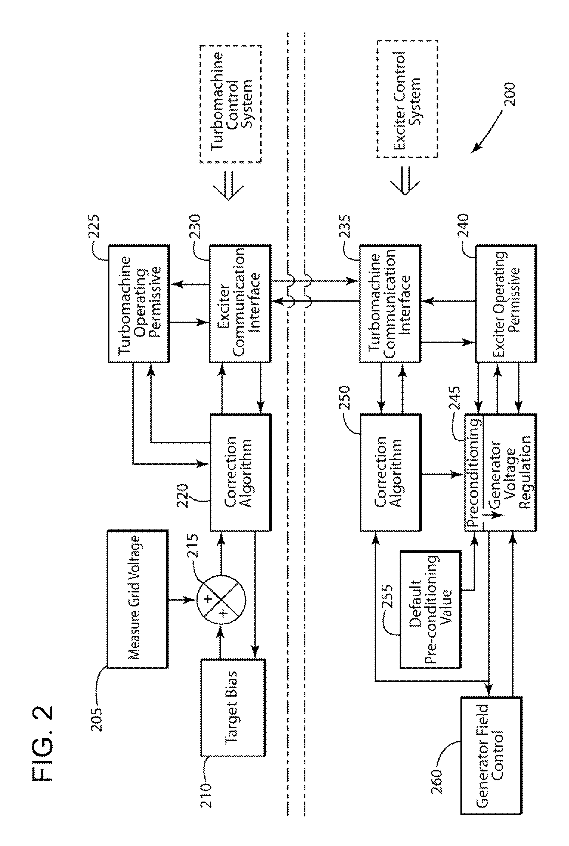
voltage loop, wherein the speed loop performs the steps of determining a voltage target of the generator field in preparation for the synchronization process; wherein the steps comprise: determining a voltage value of the grid system; applying a target bias to the voltage value; wherein the target bias assists with delivering a positive voltage to the grid system during a synchronization process; conditioning the voltage value wherein the conditioning increases the accuracy of the voltage value; determining a voltage target for the generator, wherein an exciter transforms the voltage value into the voltage target; and conditioning the voltage target to determine if the voltage target is within a preferred range; wherein the voltage loop allows the exciter to precondition a generator voltage regulator with the voltage target in preparation for synchronization as the turbomachine is accelerating to a synchronization speed.

Problems solved by technology

In addition, an undesired transient may occur when the breaker is closed due to the continued acceleration of the turbomachine.
There are a few issues with the current synchronization process.
In some applications, such as, but not limiting of, Fast Start or Rapid Response, variations in synchronization process time may be unacceptable.
This may prevent the powerplant from meeting operational requirements.

Method used


Image

  • Method of synchronizing a turbomachine generator to an electric grid
  • Method of synchronizing a turbomachine generator to an electric grid
  • Method of synchronizing a turbomachine generator to an electric grid

Examples


Embodiment Construction

[0014]The present invention has the technical effect of reducing the time associated with a synchronization process of a generator integrated with a powerplant machine. Embodiments of the present invention may actively adjust the acceleration of a rotor of the powerplant machine, to optimally control the phase angle differential between the generator and the grid. This may facilitate a consistently faster synchronization time. Embodiments of the present invention may serve to consistently reduce the power transient commonly associated with the synchronization process.

[0015]An embodiment of the present invention may seek to match the generator and grid voltages before the powerplant machine reaches the grid matching speed during the start-up process. An embodiment of the present invention may provide a predictive algorithm, or the like, to control the acceleration rate of the powerplant machine to target a particular phase angle differential between the powerplant machine and the gri...


PUM


Abstract

An embodiment of the present invention may seek to match the generator and grid voltages before the powerplant machine reaches the grid matching speed during the start-up process. An embodiment of the present invention may provide a predictive algorithm, or the like, to control the acceleration rate of the powerplant machine to target a particular phase angle differential between the powerplant machine and the grid when the powerplant machine reaches the grid matching speed. Here, the phase angle difference may be targeted such that a generator breaker may be closed immediately after the powerplant machine accelerates beyond the grid matching speed. This may avoid the generator experiencing a phase angle differential, which may add to the power transient associated with the generator breaker closure.

Description

BACKGROUND OF THE INVENTION[0001]This application is related to commonly-assigned U.S. patent application Ser. No. 12 / 331,824, filed Dec. 10, 2008.[0002]The present invention relates generally to the operation of a generator associated with a turbomachine, and more particularly, to a method of reducing the time to synchronize the generator to an electrical grid system (hereinafter “grid”).[0003]“Fast Start” and “Rapid Response” may be considered operating modes that require a turbomachine to export a load to a grid within a certain time after an operator initiates a start of that turbomachine. Fluctuating energy demand is a major factor in determining when the turbomachine operates. Turbomachines are commonly idled until sufficient demand requires operation. When demand requires operation, the turbomachinc performs a start-up process before exporting the desired electricity.[0004]Generally, a synchronization process requires that three parameters of the generator be within an accept...

Claims


Application Information

Patent Timeline
Patent Type & Authority Patents(United States)
IPC IPC(8): F02N11/00H02P9/08
CPCF01D25/00F05D2220/76H02J3/40H02P9/08
Inventor MATERS, JOHN C.CUNNINGHAM, JOHN N.
Owner GENERAL ELECTRIC CO
Why Eureka
Try Eureka