Display device having image pickup function and two-way communication system

a technology of two-way communication and display device, applied in the field of display device, can solve the problems of inability to apply the device the quality of the display screen (display plane) which is viewed by a user, and the device cannot be applied to a portable electronic device, etc., and achieve the effect of not degrading the image quality

Inactive Publication Date: 2011-03-29
SEMICON ENERGY LAB CO LTD
View PDF54 Cites 22 Cited by
  • Summary
  • Abstract
  • Description
  • Claims
  • Application Information

AI Technical Summary

Benefits of technology

[0013]In view of the foregoing problems, the invention provides a compact and lightweight display device having an image pickup function and a two-way communication system which can shoot an image of an object (user, for example) and display an image at the same time without degrading image quality by disposing a semi-transmitting mirror or the like which blocks an image on the display screen (display plane).
[0014]In addition, the invention provides a compact and lightweight display device having an image pickup function and a two-way communication system which can display an image and shoot an image of a user as an object while securing an eye focus of the user who is viewing the displayed image.

Problems solved by technology

However, according to the Patent Document 1, it requires a special screen as well as an image pickup device and a projector display device, leading to a large and heavyweight device.
Therefore, such a device cannot be applied to a portable electronic device.
Therefore, quality of the display screen (display plane) which is viewed by a user is inevitably degraded.

Method used


Image

  • Display device having image pickup function and two-way communication system
  • Display device having image pickup function and two-way communication system
  • Display device having image pickup function and two-way communication system

Examples


embodiment mode 1

[0058]Described in this embodiment mode is a portable phone having a dual emission display panel as an example of a display device having an image pickup function. Note that dual emission display panel herein defined is a display panel including a pair of light-transmitting electrodes, in which light from light emitting elements are emitted to both screen sides. It may simply be referred to as a dual emission panel.

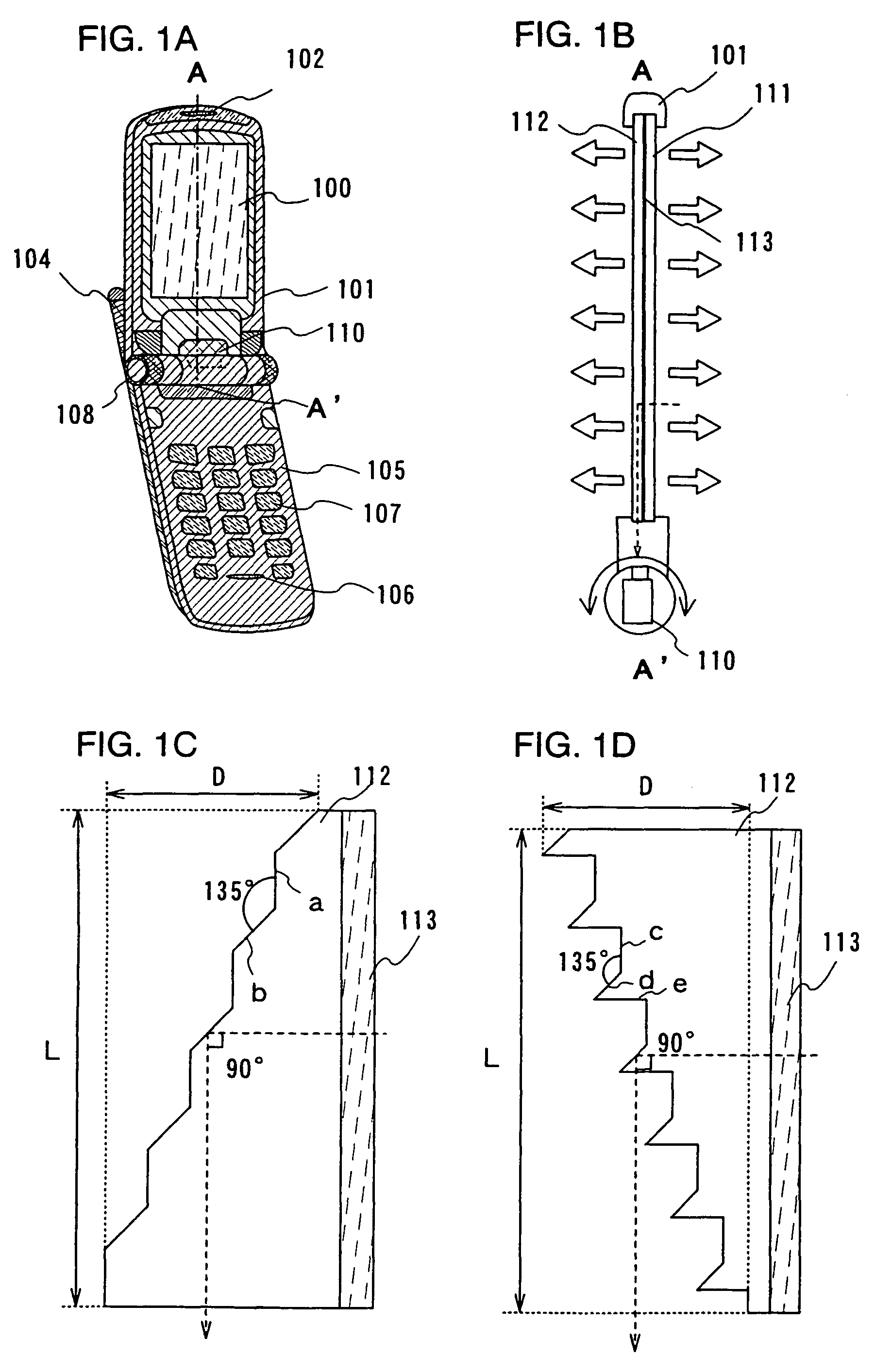
[0059]FIG. 1A illustrates an overall view of a portable phone. FIG. 1B illustrates a cross-sectional view of a dual emission panel corresponding to a display panel. FIGS. 1C and 1D each illustrates an enlarged view of a display panel.

[0060]The portable phone shown in FIG. 1A includes a dual emission display panel 100 and a first housing 101 surrounding and sandwiching an edge of the dual emission panel 100. The first housing 101 includes an audio output portion 102, an antenna 104 or the like. A second housing 105 including an audio input portion 106, an operating key 107...

embodiment mode 2

[0089]Described in this embodiment mode is a portable phone having a dual emission display panel as an example of a display device having an image pickup function, which has a different structure from that in Embodiment Mode 1.

[0090]As shown in FIG. 8A, the first housing 101 in this embodiment mode includes a fiberscope 115 for image data input. That is, a lens (objective lens) of the fiberscope 115 is disposed in the rear (on the back) of the dual emission panel 100 in the first housing 101. The fiberscope 115 is led out to the second housing 105 through the hinge 108 so as to be connected to the image pickup device 110. Note that the image pickup device 110 may be disposed in the first housing 101 as well. That is, a fiberscope for transmitting an image to the image pickup device 110 through a lens may be used as shown in FIG. 8A. In addition, the diameter, the number of lenses, or the position of the fiberscope 115 may be set appropriately.

[0091]The second housing 105 includes a ...

embodiment mode 3

[0103]Described in this embodiment mode is a videophone system having a dual emission display panel as an example of a display device having an image-pickup function.

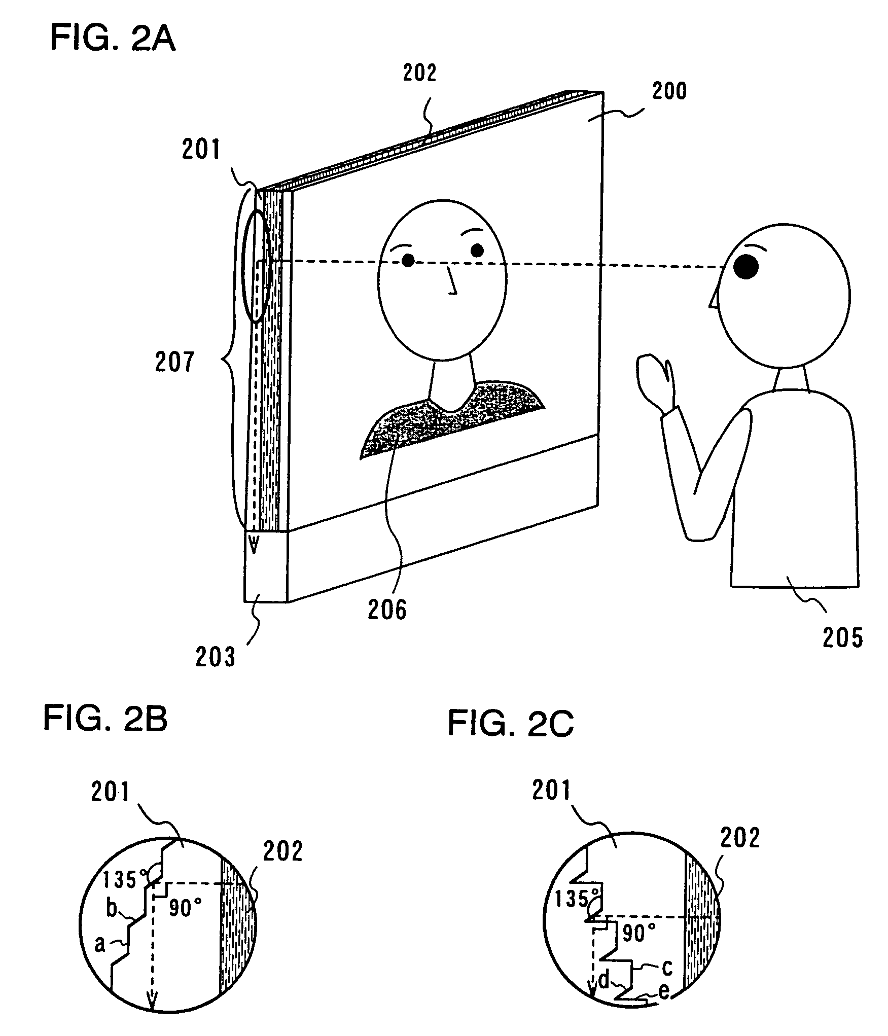
[0104]FIG. 2A illustrates an overall view of a videophone system which includes a display panel 207 having a first substrate 200, a second substrate 201 and an EL layer area 202 sandwiched between them, and an image pickup device 203 disposed at the bottom of the display panel 207.

[0105]When a user 205 faces the display panel 207 which displays an image of the other party 206, they can communicate while catching each other's eyes.

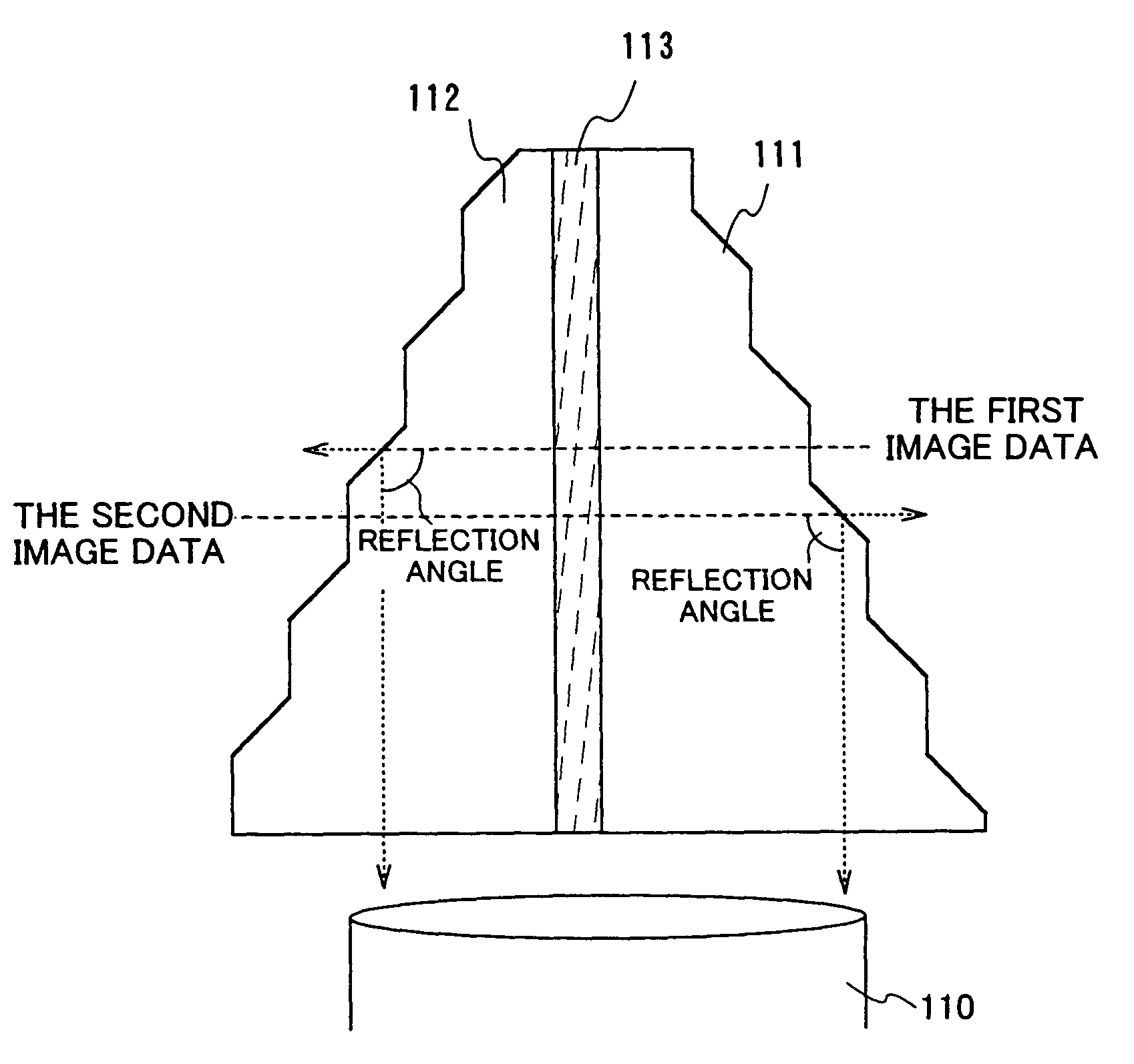
[0106]In the image pickup device 203, a microlens for condensing image data which is reflected by a reflector is disposed in conformity with the size of the display panel 207 as a lens of the image pickup device.

[0107]FIGS. 2B and 2C each illustrates an enlarged view of the display panel 207. Each figure shows a structure of the second substrate formed with depressions and projections as in FIG...


PUM

PropertyMeasurementUnit
rotation angleaaaaaaaaaa
angleaaaaaaaaaa
angleaaaaaaaaaa

Abstract

A compact and lightweight display device having an image pickup function and a two-way communication system which can shoot an image of a user as an object and display an image at the same time without degrading image quality by disposing a semi-transmitting mirror or the like which blocks an image on the display screen (display plane). The display device having the image pickup function includes a display panel capable of transmitting visible light at least and arranging display elements which can be controlled by voltage or current, and an image pickup device disposed around the display panel. The image pickup device is input with data of an image of a user or the like by a reflector, or equipped with a fiberscope bundling optical fibers.

Description

BACKGROUND OF THE INVENTION[0001]1. Field of the Invention[0002]The present invention relates to a display device having an image pickup function which can display an image and shoot an image of an object at the same time. More particularly, the invention relates to a two-way communication system which can shoot an image of a user as an object while displaying an image of the other party.[0003]2. Description of the Related Art[0004]In recent years, with the advance in speed of telecommunication networks, what is called a two-way communication system such as a videophone system and a video conference has been developed, in which two parties can communicate while viewing an image of each other.[0005]According to the two-way communication system, it is possible to shoot an image of an object (user, for example) and to display an image of the other party at the same time.[0006]For example, an image-pickup display device having a special screen which turns to be transparent or opaque acc...

Claims


Application Information

Patent Timeline
Patent Type & Authority Patents(United States)
IPC IPC(8): H04N7/14H04N5/225G02F1/13G03B15/00G09F9/00G09F9/30G09F9/35G09F9/40H01L27/32H01L51/50H04M1/02H04M1/21H04N1/00H04N5/232H04N5/262H04N5/30H04N5/66H04N5/70H05B33/14
CPCH04N1/00129H04N5/23293H04N1/00307H04N23/63H04N7/14H04N5/30G02F1/13H04N7/144
Inventor MIYAGAWA, KEISUKEYAMAZAKI, SHUNPEI
Owner SEMICON ENERGY LAB CO LTD
Why Eureka
Try Eureka