System for pressurizing fluid

a technology of pressurizing fluid and system, applied in the field of system and system for generating electricity, can solve the problems of heat loss and energy loss, and achieve the effect of relieving the weight of the turbine wheel and sha

Inactive Publication Date: 2011-04-05
PAPP EUGENE
View PDF24 Cites 7 Cited by
  • Summary
  • Abstract
  • Description
  • Claims
  • Application Information

AI Technical Summary

Benefits of technology

Yet another object of the present invention is to provide a system that produces electric power without consumption of limited natural resources, pollution, or greenhouse gas emission, and is independent of wind conditions.
Still yet another object of the present invention is to provide a system that produces electric power at a low cost.
Yet another object of the present invention is to provide a system wherein the towers are unified at the lower end with a single base enclosure providing means to maximize air speed.
Still yet another object of the present invention is to provide a system wherein the upper end of each tower can include a venturi like collar to increase air suction.
The present invention overcomes the shortcomings of the prior art by providing low cost electric power without consumption of limited natural resources, pollution, or greenhouse gas emission, and is independent of wind conditions. Additionally, the system of the present invention includes a venturi-like collar positioned at the top of one or more stacks increasing air flow.

Problems solved by technology

In a thermoelectric generating plant utilizing heat to generate electric energy and having a recirculating water system in which the water is heated during passage through the plant and must be cooled before recirculation to the plant thus causing a heat loss and resultant loss of energy; the combination therein of apparatus for recapturing a portion of the normally lost energy.

Method used


Image

  • System for pressurizing fluid
  • System for pressurizing fluid
  • System for pressurizing fluid

Examples


Embodiment Construction

The following discussion describes in detail one embodiment of the invention (and several variations of that embodiment). This discussion should not be construed, however, as limiting the invention to those particular embodiments, practitioners skilled in the art will recognize numerous other embodiments as well. For definition of the complete scope of the invention, the reader is directed to appended claims.

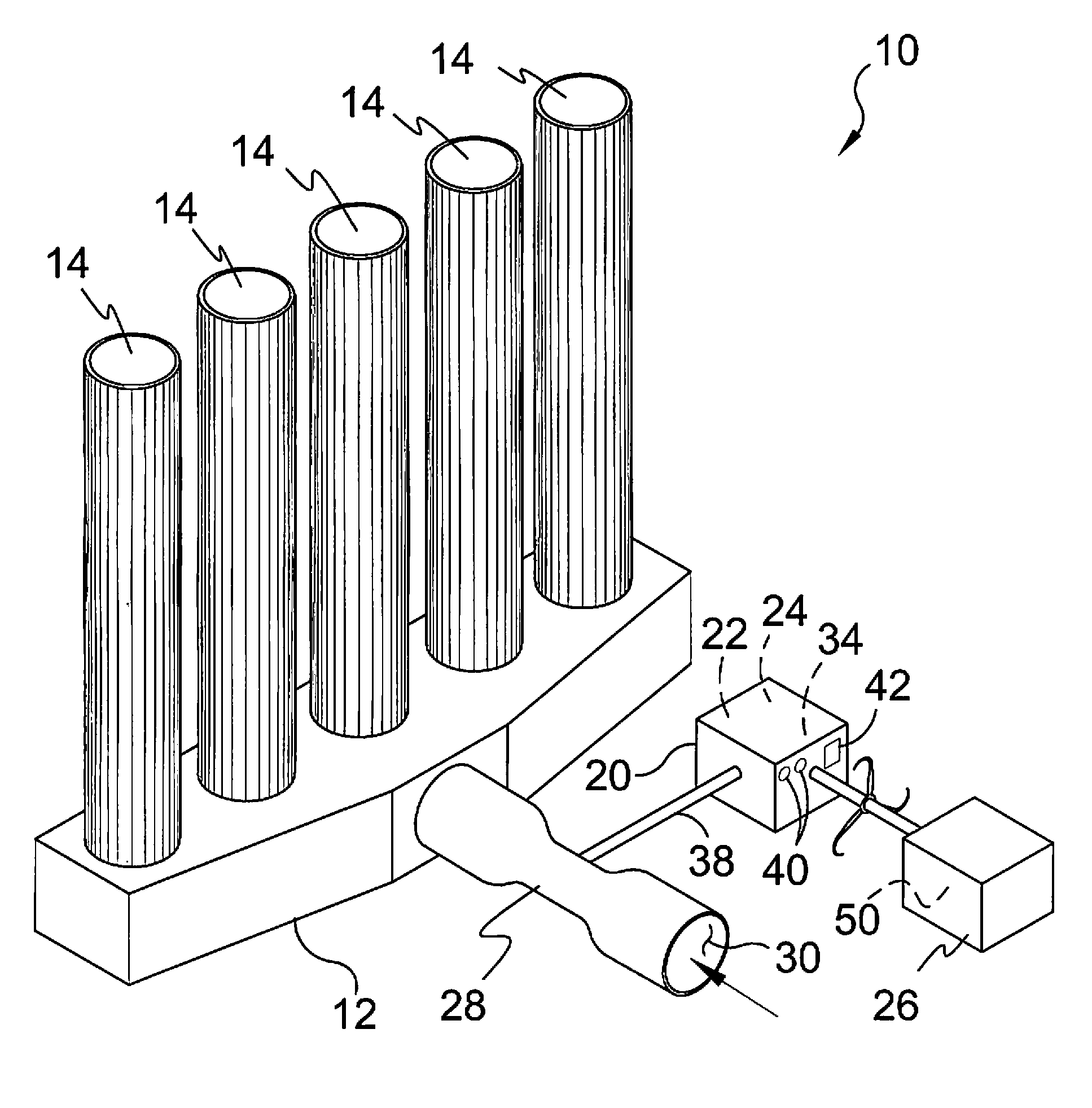
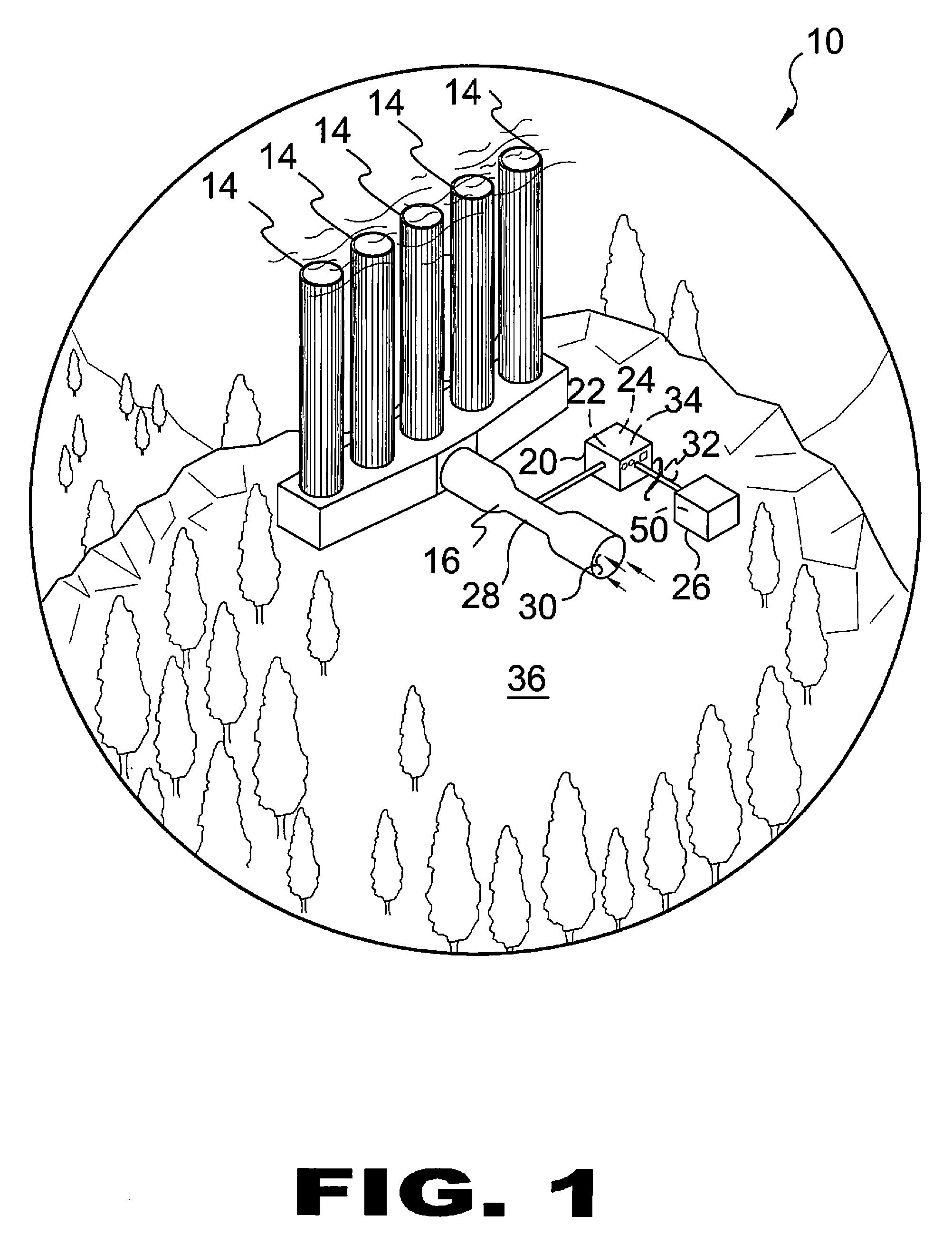
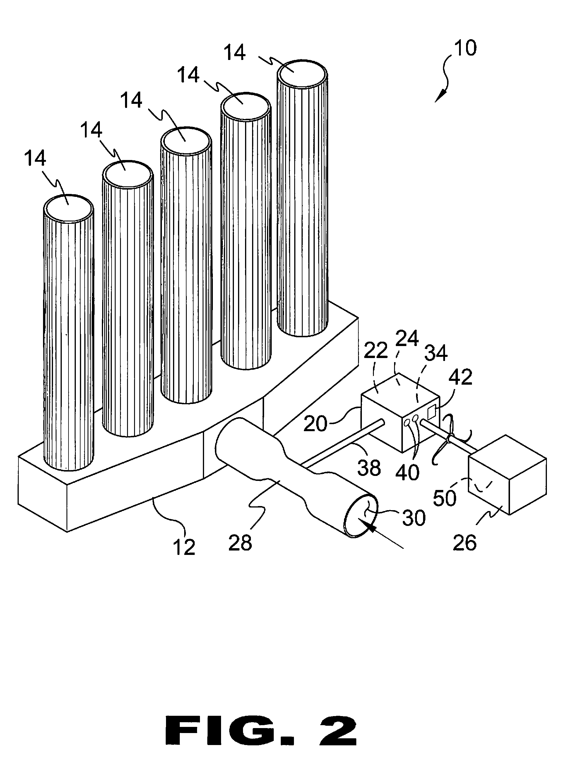
FIG. 1 is an illustrative view of the present invention 10 in use. The present invention 10 is a system for generating electricity comprising a plurality of towers 14 in communication with a common base with an air intake venturi conduit 16 extending centrally and horizontally therefrom. The air intake venturi 16 with an air intake port 30 leading to a central venturi throat 28 of smaller diameter containing an air driven turbine connected to a power storage unit 20 used to power rotor 50 of generator 26. The power storage unit 20 is comprised of an air compressor 22 or liquid p...


PUM


Abstract

A system for providing low cost fluid pressurization without consumption of limited natural resources, pollution, or greenhouse gas emission, and is independent of wind conditions. Additionally, the system of the present invention includes a venturi-like collar positioned at the top of one or more stacks increasing air flow.

Description

BACKGROUND OF THE INVENTION1. Field of the InventionThe present invention relates generally to power generation and, more specifically, to a system for generating electricity utilizing continuous reusable energy.The energy generating system of the present invention produces low cost electric power without consumption of limited natural resources, pollution, or greenhouse gas emission, and is independent of wind conditions. In turn, the energy generating system of the present invention provides improved means over existing coal and gas fixed power generation as well as nuclear plants and wind mill farms.The present invention is a system for generating electricity comprising a plurality of towers in communication with a base level conduit housing having a section of smaller diameter containing an air driven turbine connected to a power storage system used to power a generator.The towers are unified at the lower end with a single base enclosure providing means to maximize air speed. Th...

Claims


Application Information

Patent Timeline
Patent Type & Authority Patents(United States)
IPC IPC(8): F03D3/00
CPCF03D9/028F03G6/045F05B2240/131Y02E60/15F05B2260/24Y02E10/465Y02E10/728F05B2240/9111F03D9/17F03D9/25F03D9/28Y02E10/46Y02E10/72Y02E60/16Y02E70/30Y10S415/905Y10S415/909
Inventor PAPP, EUGENE
Owner PAPP EUGENE
Why Eureka
Try Eureka