Hybrid transmission

a transmission and hybrid technology, applied in the direction of engine-driven generators, transportation and packaging, transportation, etc., can solve the problems of large installation space, increased wear, and undesirable heating

Inactive Publication Date: 2011-04-05
DAIMLER AG
View PDF20 Cites 8 Cited by
  • Summary
  • Abstract
  • Description
  • Claims
  • Application Information

AI Technical Summary

Benefits of technology

[0016]In a hybrid transmission for a hybrid motor vehicle, with split power driving ranges, discrete gear steps and two electric drive motors (33, 34), a transmission arrangement is provided which results in low rotational speeds of the transmission elements, in particular of the planets while at the same time, the electric drive motors (33, 34) are disposed adjacent to one another at the input end of the trans-mission next to an internal combustion engine to which the transmission is connected.
[0018]Instead, in accordance with the invention, use is made of the fact that the input end of the hybrid gearbox is generally flanged to an internal combustion engine, the internal combustion engine which has a relatively large cross-section. Consequently, at a transition from the internal combustion engine to the two electric drive assemblies, the drive train cross-section does not need to be increased, but may even decrease. This is followed, sometimes with a further tapering of the transmission housing structure including the differentials, so that, with an increasing distance from the internal combustion engine, the drive train can be tapered even further. The cross-sectional configuration of as far as possible conventional tapering vehicle can therefore remain as the hybrid transmission is adapted to that shape.
[0026]According to a particular embodiment of the hybrid transmission according to the invention, (at least) one shift element is present, via which the first differential and the second differential can be blocked each individually and with one another. This is, in particular, a coupling element which, in the activated state, connects in each case two of the six transmission elements of the first and the second differential to one another. With a coupling of this type, a particularly simple connection of the internal combustion engine to the first electric drive motor is possible; no rolling gearwheel connections, which may lead to losses of efficiency, need to be interposed in this case. Coupling means of this type may be utilized, on the one hand, for superposing the drive powers of the electric drive motor and of the internal combustion engine. On the other hand, the internal combustion engine can be driven by the electric drive motor in order to start the internal combustion engine. When the power of the internal combustion engine is not needed for driving the vehicle, furthermore, electric power generated by one or both electric drive motors, then operating as generators, can be fed back into a battery.
[0028]If a change between two adjacent continuous driving ranges takes place at a synchronous point, a synchronizing power of the actuated shift elements, which may lead to increased shift times and / or to increased wear, can be reduced or avoided. Depending on the desired operation of the motor vehicle, a change from a first continuous driving range into a discrete gear may also take place without a synchronization of the transmission elements effective in the particular gear.
[0031]A further solution for achieving the object of the invention is provided by a motor vehicle including a hybrid transmission of the type described above which is integrated into a drive train having a standard drive configuration. The transverse cross-section of the drive train decreases along the longitudinal axis of the drive train with increasing distance from the internal combustion engine through the electric drive assemblies to the differentials, so that the drive train has a tapered configuration in this region. A drive train of this type can be integrated in a space-saving way into a vehicle tunnel tapering down between the electric drive assemblies and the differentials. It thereby also becomes possible, where appropriate, that the hybrid transmission can be moved further to the rear into the motor vehicle, so that construction compartment space is freed in the engine space by virtue of the configuration according to the invention.

Problems solved by technology

If, on the other hand, the electric drive motors with their large diameters would be arranged relatively far from the engine in the direction of the output, the hybrid transmission housing, spaced apart from the internal combustion engine, would require a large installation space, which is disadvantageous particularly in the region of a vehicle body tunnel and / or in the region of a passenger compartment.
This results, for example, inundesirable heating,increased wear,increased bearing stresses and / orincreased noise generation.

Method used


Image

  • Hybrid transmission
  • Hybrid transmission

Examples


Embodiment Construction

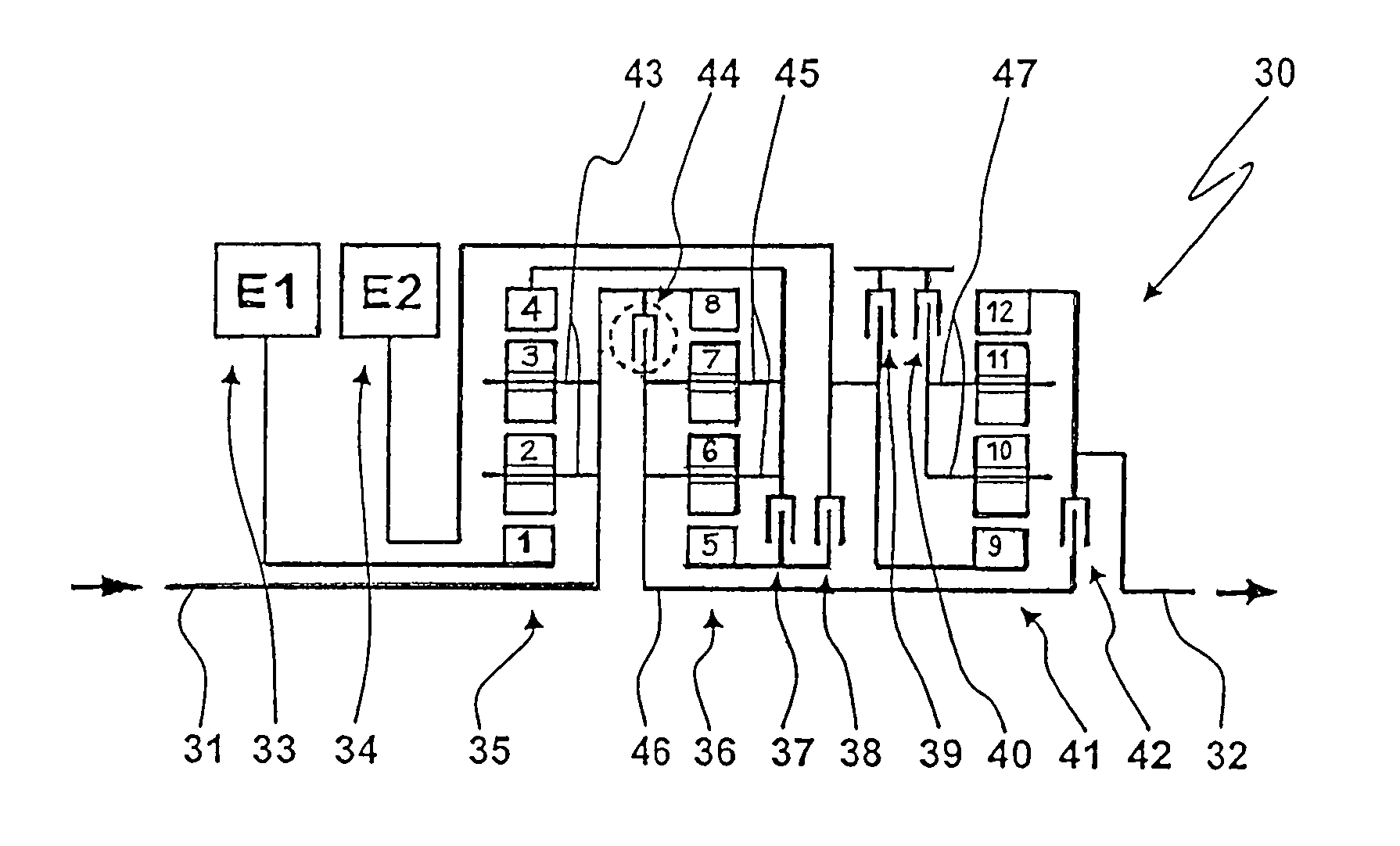
[0036]The hybrid transmission 30 is preferably used in a motor vehicle having a standard drive which is installed in the vehicle longitudinal direction and is integrated at least partially into a vehicle body tunnel.

[0037]The hybrid transmission 30 comprises an input shaft 31, which is drive-connected to an internal combustion engine, and an output shaft 32, which is drive-connected to wheels of the motor vehicle.

[0038]In the hybrid gearbox 30,[0039]a first electric drive assembly 33,[0040]a second electric drive assembly 34,[0041]a second differential 35,[0042]a first differential 36,[0043]clutches 37, 38,[0044]brakes 39, 40,[0045]a third differential 41, and[0046]a clutch 42

are disposed in the above order, in axially successive planes and essentially coaxially with respect to one another, between the transmission input shaft 31 and the transmission output shaft 32.

[0047]The transmission input shaft 31 extends concentrically through the second differential 35 and is fixedly drive-c...


PUM


Abstract

In a hybrid transmission for a hybrid motor vehicle, with split power driving ranges, discrete gear steps and two electric drive motors (33, 34), a transmission arrangement is provided which results in low rotational speeds of the transmission elements, in particular of the planets while at the same time, the electric drive motors (33, 34) are disposed adjacent to one another at the input end of the transmission next to an internal combustion engine to which the transmission is connected.

Description

[0001]This is a Continuation-In-Part application of pending International Patent Application PCT / EP2006 / 006115 filed Jun. 24, 2006 and claiming the priority of German Patent Application 10 2005 030 420.6 filed Jun. 30, 2005.BACKGROUND OF THE INVENTION[0002]The invention relates to a hybrid transmission with at least two split power ranges and two electric drive motors for a hybrid motor vehicle and furthermore to a hybrid motor vehicle having a hybrid transmission of this type.[0003]Hybrid transmissions for motor vehicles, which have a plurality of split power drive ranges, discrete gear steps and, in addition to an internal combustion engine, two electric drive motors, are known, for example, from the publications U.S. Pat. Nos. 5,904,631, 6,478,705 B1, 6,358,173 B1, 6,090,005, 6,743,135 B2, 6,551,208 B1, EP 0 967 102 B1, U.S. Pat. Nos. 5,931,757, 6,022,287 and applicant's patent application DE 102004053044.[0004]Hybrid transmissions of this type make it possible to operate the mot...

Claims


Application Information

Patent Timeline
Patent Type & Authority Patents(United States)
IPC IPC(8): F16H3/72B60K6/26B60K6/365B60K6/40B60K6/445
CPCB60K6/26B60K6/365B60K6/40B60K6/442B60K6/445F16H3/728Y02T10/6239F16H2037/102F16H2037/104F16H2037/106F16H2200/201Y02T10/6234B60L50/15Y02T10/62Y02T10/7072Y02T10/64
Inventor GOLDSCHMIDT, STEFANKROLO, ANNAPAETZOLD, REINERZIEGELE, JAN-PETER
Owner DAIMLER AG
Why Eureka
Try Eureka