Method and improvement to saw system used for cutting I-joists to size

a saw system and joist technology, applied in the direction of metal sawing devices, girders, manufacturing tools, etc., can solve the problems of increasing construction costs, reducing so as to improve the strength of the finished floor, improve the efficiency of construction, and improve the effect of construction efficiency

Inactive Publication Date: 2011-04-05
ROBELL GLENN
View PDF2 Cites 3 Cited by
  • Summary
  • Abstract
  • Description
  • Claims
  • Application Information

AI Technical Summary

Benefits of technology

pt and immediately strong. Another advantage of the present invention is that the protective release liner over the adhesive layer is configured and positioned to prevent adhesive degradation prior to I-joist installation, either from casual contact with other objects during transport and handling that could lead to the removal of indiscriminate portions of the adhesive layer via nicking or gouging, as well as various potentially degrading contact of the adhesive layer with airborne particles, other debris, moisture, and direct solar radiation during the transport of the I-joists enhanced with the present invention, their storage, and/or while they are present on a construction site waiting for installation. Further, the cost of the automated application of the present invention adhesive layer and protective release liner to I-joists prior to their delivery to a construction jobsite is very low when compared to the on-site labor cost needed to achieve the enhanced strength in a finished floor that is mandated by most local codes. A further advantage of the low cost present invention' in areas subject to severe weather conditions, such as but not limited to areas frequently experiencing hurricanes, typhoons, and tornados, the present invention can provide a means for strengthening the connection between I-joists and adjacent sheer panels in roof construction for a very low material and labor cost when compared to on-site manual adhesive application, which is not currently required by building codes or routinely done in today's residential and commercial construction. No method or improvement to I-joist cutting saw systems is known that provides the valued-enhanced product or other advantages of the present invention.
The primary object of this invention to provide a method and improvement to saw systems used to cut raw I-joists prior to their delivery to a construction jobsite, whereby I-joists are enhanced by the automated application of an adhesive layer and a protective liner configured and dimensioned to achieve a stronger and more consistent bond between the I-joists and adjacent sheer panels commonly used in today's residential and commercial construction industry. Another object of this invention is to provide a method and improvement to saw systems used to cut raw I-joists prior to their delivery to a construction jobsite that produces adhesive-enhanced I-joists that meet local building codes for floor construction which require the use of adhesives, and does so with a very low cost when compared to the labor cost of manual adhesive application. It is a further object of this invention to provide a method and improvement to saw systems used to cut raw I-joists prior to their delivery to a construction jobsite that produces adhesive-enhanced I-joists that promptly bond with adjacent sheer panels, achieve a more consistent bond between I-joists and adjacent sheer panels in finished construction than manually applied adhesives, and are not compromised by I-joist installation during inclement weather.
The present invention method and saw system improvement, when properly implemented, will provide I-joists enhanced with an adhesive layer and a protective liner that are able to achieve

Problems solved by technology

However, there are at least two important disadvantages to the on-site manual application of liquid adhesives during floor construction.
One such disadvantage is that it is labor intensive and can significantly increase construction cost.
The second such disadvantage is that there is the potential for inconsistent application, whereby, if too little adhesive is used, maximum sheer and strength in the finished construction project is not achieved.
In the alternative, if too much adhesive is applied, material c

Method used


Image

  • Method and improvement to saw system used for cutting I-joists to size
  • Method and improvement to saw system used for cutting I-joists to size
  • Method and improvement to saw system used for cutting I-joists to size

Examples


Embodiment Construction

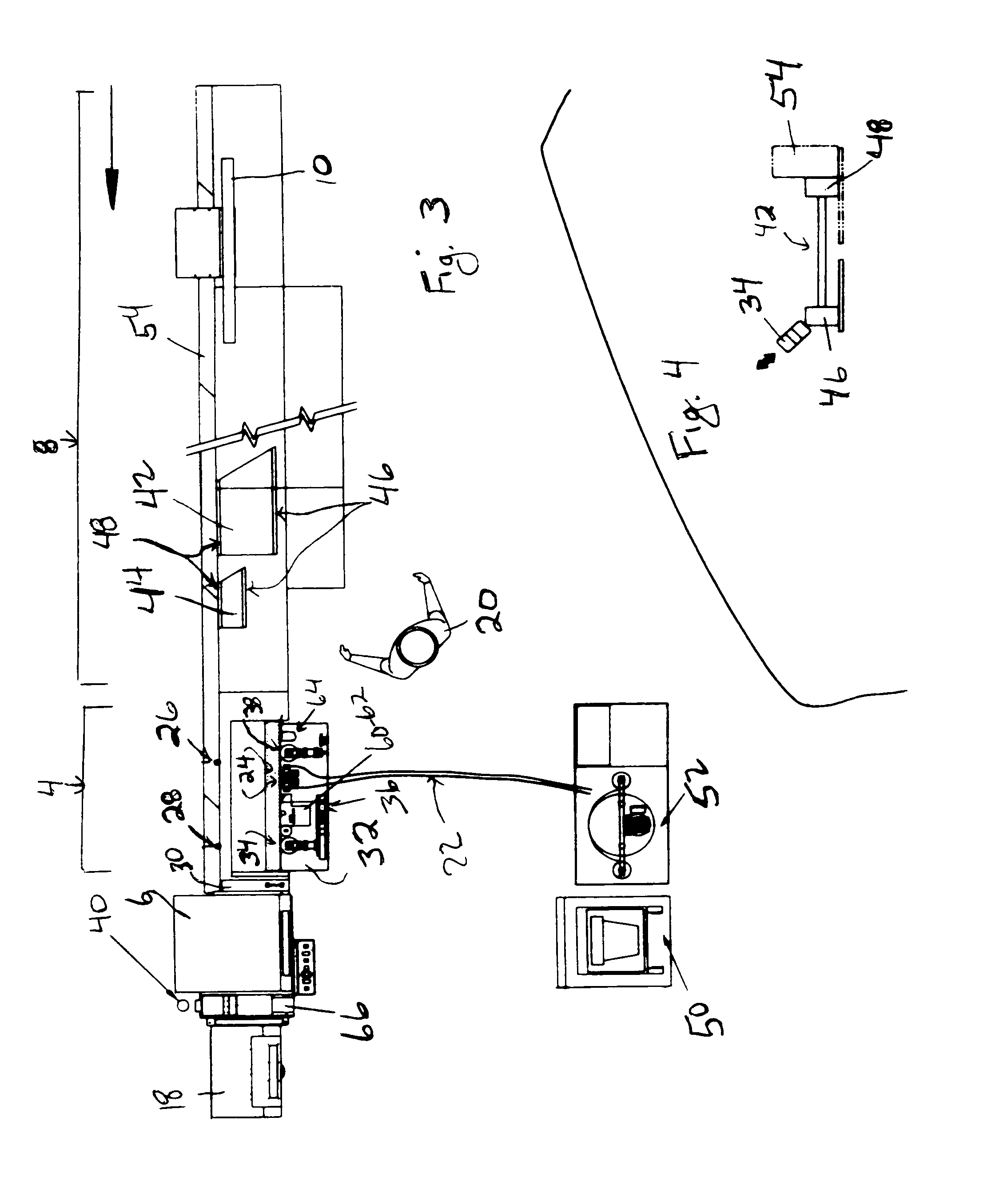
The present invention provides value-added construction materials and a method that achieves a more consistent bond between structural framing components, such as but not limited to smaller I-joist 44 and larger I-joist 42 in FIG. 3, and adjacent sheer panels (not shown) to achieve maximum overall strength in finished construction. Typically in the present invention, but not limited thereto, framing components, such as roof trusses, floor trusses, floor and ceiling joists, walls studs, roof and wall sheathing, and floor panels, will have adhesive (shown in FIG. 8 by the number 58) applied during manufacture to at least one surface, with the adhesive being configured and dimensioned to meet up with the intended contact area of the opposing component to which it will be joined after adhesive 58 has been pressed into its final thickness dimension. For example, but not limited thereto, in today's construction when roof trusses are laid out two foot on center, there is no adhesive betwee...


PUM

PropertyMeasurementUnit
Angleaaaaaaaaaa
Thicknessaaaaaaaaaa
Sizeaaaaaaaaaa

Abstract

A method and an improvement to saw systems configured to convert raw I-joists from inventory to pre-cut sizes and/or cut routed patterns in I-joists for utility pass-through applications prior to their shipment to a construction site or return to inventory, whereby a controlled amount of adhesive and a protective liner are automatically and successively applied to the top flange of each I-joist. The saw system improvement comprises coordinated mechanical, electrical, and pneumatic components.

Description

CROSS-REFERENCES TO RELATED APPLICATIONSNoneBACKGROUND1. Field of the InventionThis invention relates to the field of saw systems used to cut I-Joists to size, specifically to a method and an improvement to saw systems, such as but not limited to the Sawtek saw system used by Boise Cascade that is configured to convert raw I-joists from inventory to pre-cut sizes and / or cut routed patterns in I-joists for utility pass-through applications prior to their shipment to a construction site, whereby the prior art saw system is enhanced by the addition of equipment configured for applying a controlled amount of adhesive and a protective liner automatically and successively to the top flange of each I-joist, and wherein such application preferably takes place before the I-joists are cut. The present invention preferably comprises coordinated mechanical, electrical, and pneumatic components to achieve the adhesive and protective liner applications.2. Description of the Related ArtIn today's ...

Claims


Application Information

Patent Timeline
IPC IPC(8): B29C65/00B29C65/48B32B37/26B32B37/12B32B37/02B32B37/00
CPCB23D45/003B29C63/02E04C3/14Y10T156/12B29C2063/485B29L2031/003Y10T156/1056Y10T156/1352Y10T156/1322Y10T156/1317Y10T156/1057Y10T156/1062Y10T156/1348Y10T156/1052B29C63/0056
Inventor ROBELL, GLENN
Owner ROBELL GLENN
Why Eureka
Try Eureka