Pressure generation device

a pressure generation device and pressure generation technology, applied in the direction of positive displacement liquid engine, piston pump, gasket, etc., can solve the problems of increasing poor mounting in the vehicle, and difficulty in reducing so as to reduce the size and cost reduce the size of the pressure-generating device, and reduce the effect of effective utilization

Inactive Publication Date: 2011-04-12
TOYOTA JIDOSHA KK
View PDF36 Cites 1 Cited by
  • Summary
  • Abstract
  • Description
  • Claims
  • Application Information

AI Technical Summary

Benefits of technology

In the pressure-generating device according to the present invention, the rotary shaft portion of the rotary member is supported rotatably in the support member via the bearing, and the pumping member (piston) is attached to the rotary shaft portion of the rotary member in a unitarily rotatable manner and in such a manner as to be able to perform a pumping action and, in cooperation with the rotary shaft portion, forms the pump chamber therebetween. Accordingly, not only does the rotary member not require a balance weight for achieving balance of rotation, but also the pressure-generating device can be configured compact within the support member, thereby enabling a reduction in the size of the pressure-generating device.
The present invention can also be embodied such that the rotary shaft portion is rotatably supported by the support member via a first bearing and a second bearing which are axially spaced a predetermined distance apart from each other. In this case, the first bearing and the second bearing can ensure support rigidity in supporting the rotary member by the support member. The pressure-generating device can also be configured such that the motion-converting mechanism intervenes between the first bearing and the second bearing. This enables effective utilization of the space between the first bearing and the second bearing as a space for accommodating the motion-converting mechanism, so that the pressure-generating device can be configured compact.
The present invention can also be embodied such that a first seal member and a second seal member for sealing the first and second bearings intervene between the rotary shaft portion and the support member in such a manner as to sandwich the motion-converting mechanism and the first and second bearings therebetween. In this case, the first seal member and the second seal member can seal the first and second bearings as well as the motion-converting mechanism; i.e., the seal members can be used in common, so that the pressure-generating device can be reduced in size and cost.

Problems solved by technology

Thus, the radius of the inclined plane of the cam member in contact with one end of the piston must be equal to or greater than the amount of the radial offset of the axis of the piston, thereby raising difficulty in reducing the size of the pressure-generating device and thus involving poor mountability in a vehicle.
This also raises difficulty in reducing the size of the pressure-generating device.

Method used


Image

  • Pressure generation device
  • Pressure generation device
  • Pressure generation device

Examples


first embodiment

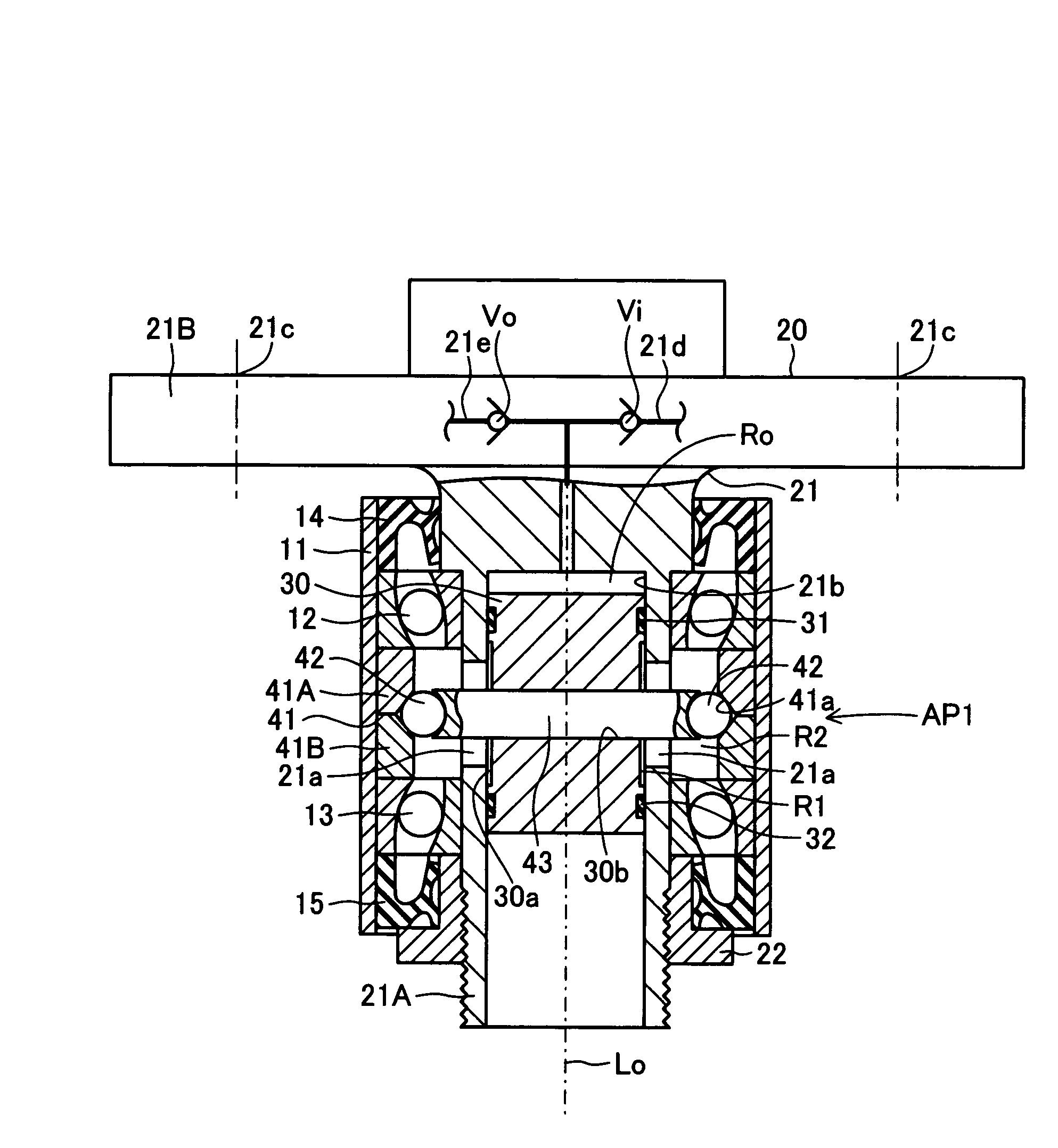
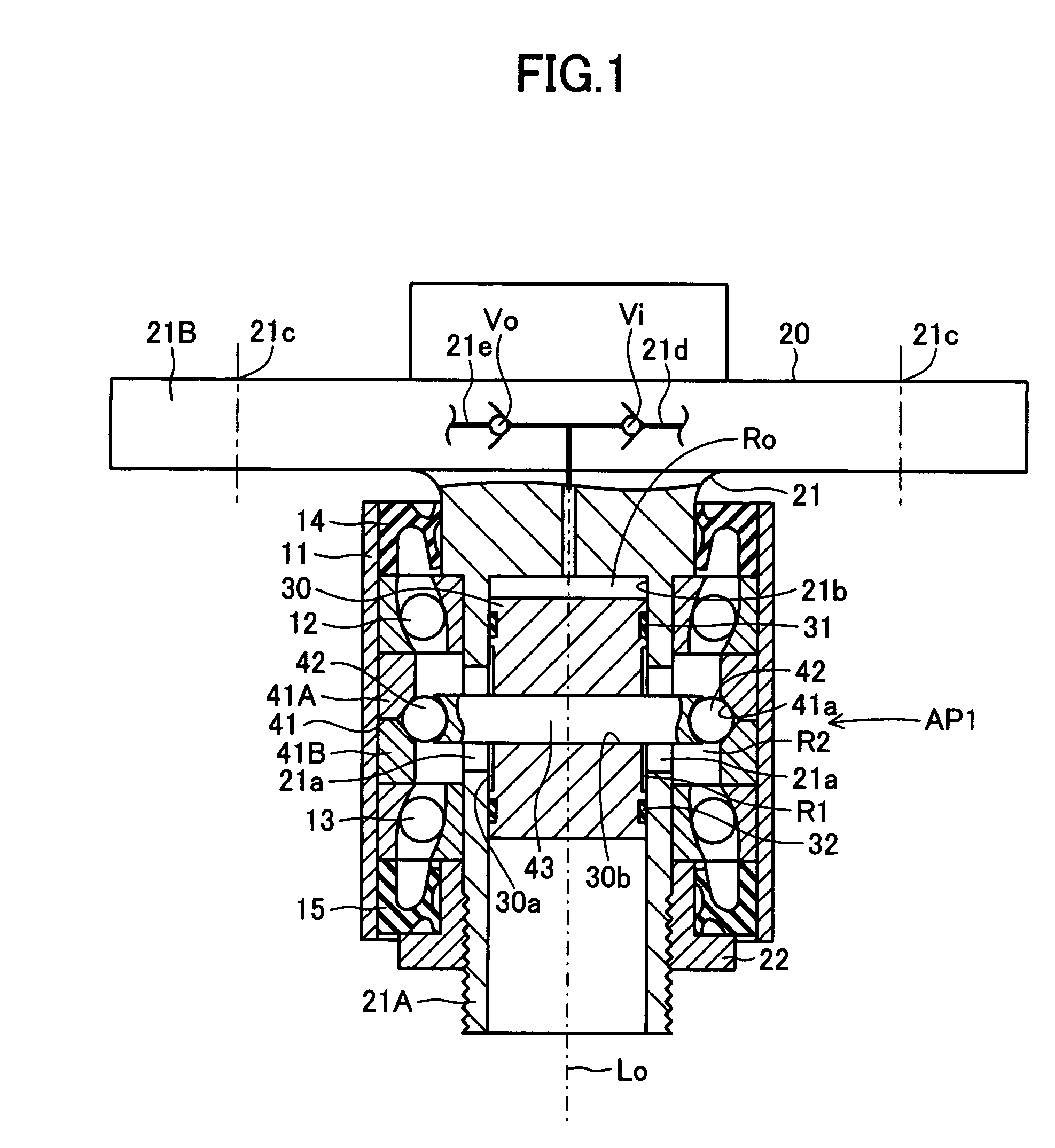
In the thus-configured pressure-generating device AP1 of the first embodiment, when the axle hub 20 rotates in relation to the cylindrical support portion 11, the piston 30, the rod 43, and the cam followers 42 rotate unitarily with the axle hub 20 and make relative rotation in relation to the cam member 41 to thereby move axially. Accordingly, the rotary motion of the axle hub 20 can be converted to the reciprocating motion of the piston 30. The reciprocating motion of the piston 30 can increase and decrease the volume of the pump chamber Ro. Thus, air can be introduced into the pump chamber Ro through the suction path 21d in which the suction check valve Vi is installed, and air can be discharged from the pump chamber Ro through the discharge path 21e in which the discharge check valve Vo is installed. The discharged air (pressurized air) can be supplied into the tire air chamber (not shown) of a wheel attached to the axle hub 20.

In the pressure-generating device AP1 of the first ...

second embodiment

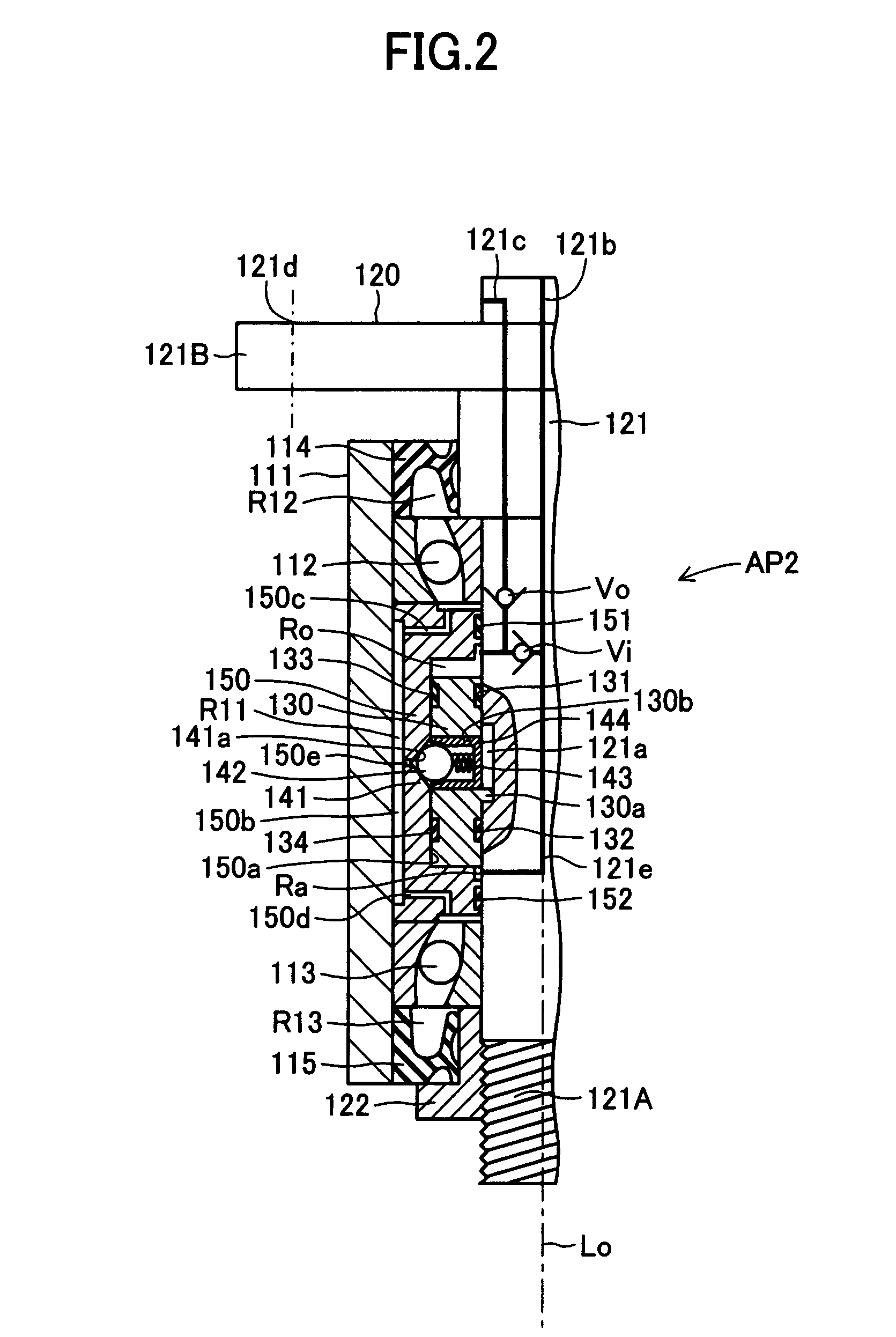
In the thus-configured pressure-generating device AP2 of the second embodiment, when the axle hub 120 rotates in relation to the cylindrical support portion 111, the piston 130 and the cam follower 142 rotate unitarily with the axle hub 120 and make relative rotation in relation to the cylindrical cam 141 to thereby move axially. Accordingly, the rotary motion of the axle hub 120 can be converted to the reciprocating motion of the piston 130. The reciprocating motion of the piston 130 can increase and decrease the volume of the pump chamber Ro. Thus, air can be introduced into the pump chamber Ro through the suction path 121b in which the suction check valve Vi is installed, and air can be discharged from the pump chamber Ro through the discharge path 121c in which the discharge check valve Vo is installed. The discharged air (pressurized air) can be supplied into the tire air chamber (not shown) of a wheel attached to the axle hub 120.

In the pressure-generating device AP2 of the se...

third embodiment

The third embodiment has air chambers R22 (see FIG. 5), which collectively serve as a volume-change-reducing means for reducing a change in volume of the annular space R21 associated with the reciprocating motion of the two pistons 230. The air chambers R22 decrease in volume as the volume of the annular space R21 decreases, and increase in volume as the volume of the annular space R21 increases. The air chambers R22 are implemented by respective air bags 250, which are attached to the outer circumference of the rotary shaft portion 221A in a unitarily rotatable manner. The air bags 250 are formed from an elastic, airtight material such as rubber and confine compressed air therein. The air bags 250 shrink as the inner pressure of the annular space R21 increases in association with a reduction in volume of the annular space R21, and inflate as the inner pressure of the annular space R21 drops in association with an increase in volume of the annular space R21. This reduces the magnitu...


PUM


Abstract

A pressure-generating device includes an axle hub having a rotary shaft portion supported rotatably in a nonrotatable cylindrical support portion via bearings; a piston attached to the rotary shaft portion in a unitarily rotatable manner and so as to perform a pumping action, and, in cooperation with the rotary shaft portion, forming a pump chamber therebetween; a cam member and cam followers for converting a rotary motion of the axle hub in relation to the cylindrical support member to the pumping action of the piston; a suction path formed in the axle hub and enabling introduction of air into the pump chamber; and a discharge path formed in the axle hub and enabling discharge of air from the pump chamber.

Description

TECHNICAL FIELDThe present invention relates to a pressure-generating device; for example, a pressure (air pressure) generating device capable of supplying pressurized air to a tire air chamber of a wheel including a disc wheel and a tire, the disc wheel being held on an axle hub of a vehicle and being rotatable with the axle hub, and the tire being mounted on the disc wheel to thereby form the tire air chamber therebetween.BACKGROUND ARTA pressure-generating device of this kind is disclosed in, for example, Japanese Patent Application Laid-Open (kokai) No. 11-139118. In a pressure-generating device (air pressure regulator for tire) described in this publication, a pump unit is disposed on a member which rotates with an axle for rotatably driving an axle hub of a vehicle; the pump unit performs a reciprocating motion in the axial direction of the axle; and one end of a piston of the pump unit abuts an inclined plane of a cam member that is nonrotatable in relation to a wheel. The pi...

Claims


Application Information

Patent Timeline
Patent Type & Authority Patents(United States)
IPC IPC(8): F04B17/06
CPCF04B1/0413F04B9/042F04B1/047Y10T74/18312B60C23/127B60C23/137B60B27/0015B60B27/0005B60B27/001B60B27/0073F05B2260/506F05B2240/50
Inventor ISONO, HIROSHI
Owner TOYOTA JIDOSHA KK
Why Eureka
Try Eureka