
Device and method for locating anatomical cavity in a body

a technology for locating an anatomical cavity and a body, which is applied in the direction of positive displacement liquid engine, application, tomography, etc., can solve the problems of needle shooting through (too far) when the anatomical cavity is reached, the risk of the needle being introduced too far, and the risk of the anatomical cavity being reached. to achieve the effect of eliminating or at least reducing the above drawback

Active Publication Date: 2011-04-12
APAD OCTROOI
View PDF24 Cites 32 Cited by
  • Summary
  • Abstract
  • Description
  • Claims
  • Application Information

AI Technical Summary

Benefits of technology

[0010]It is an object of the present invention to provide an improved device for locating an anatomical cavity in which the above drawback is eliminated or at least reduced.SUMMARY OF THE INVENTION
[0012]In the device according to the invention, the pressure is made continuously available to the person who is handling the device and to any onlookers who may be present during the introduction of the needle into the body by means of the acoustic signal, which is representative of the prevailing pressure and therefore of the pressure signal. The person who is handling the device can therefore use his hearing to obtain instantaneous pressure data continuously, which data is directly representative of the pressure in the needle which is coupled to the reservoir. Consequently, the person who is handling the device can continuously direct his eyes at the needle and does not have to work on the basis of visual information and / or tactile information. A particular advantage is that the interpretation of the measured pressure is the responsibility of the person who is handling the device, rather than of a processor, and therefore it is possible to draw an interpretation with regard to intra-individual pressure variations for each case.
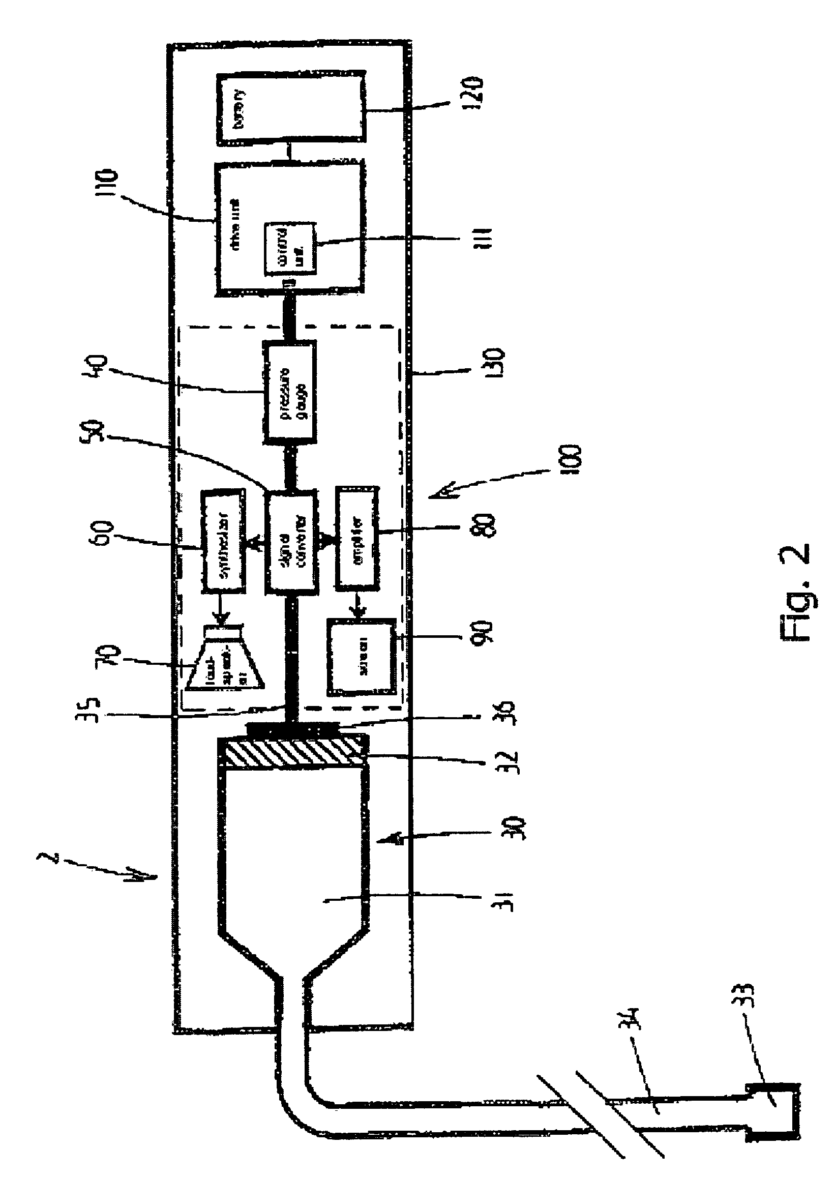
[0015]When using the device according to the invention, the person who is handling the device continuously receives the instantaneous pressure data on the basis of his hearing, and therefore there is no need to feel the pressure in the fluid. The use of automatic pump means has the major advantage that the person who is handling the device can use both hands to move the point of the needle towards the anatomical cavity. When both hands are being used, the person who is handling the device is able to introduce the needle in a more controlled way than if only one hand is used for this purpose. Moreover, he does not now have to exert any force in order to generate the pressure, but rather only has to exert force on the needle.
[0017]The fact that the drive unit displaces the plunger, preferably at a constant rate, means that the force which is exerted on the plunger by the automatic pump means will always have to vary, since the point of the needle is constantly moving through different types of tissue as it is being introduced. In the case of a relatively firm tissue, the fluid which emerges from the needle will be subject to more resistance from the tissue than in the case of a soft tissue. When the point of the needle reaches the anatomical cavity, the fluid will flow into the anatomical cavity virtually without resistance, and therefore scarcely any force has to be exerted on the plunger. This consequently results in a considerable drop in the pressure of the fluid.
[0018]The risk of the point of the needle being introduced too far is considerably reduced compared to the device which is known from EP 0 538 259.
[0019]The device according to the invention is eminently suitable for use for training purposes, in particular for training medical personnel. An instructor can easily monitor the actions of a student or trainee and provide suitable instructions, since he can always hear information about the pressure state at the point of the needle. If the preferred embodiment with the drive means is being used, it has the additional advantage that the student or trainee only has to concentrate on the movement of the needle and can use both hands to do this.

Problems solved by technology

A further drawback of the device and method which are known from EP 0 538 259 relates to the risk of the point of the needle being introduced too far.
Although the known device reduces this risk, since the feeling of the person who is handling the device is assisted by the warning signals, the risk of the needle shooting through (too far) when the anatomical cavity is reached as a result of one hand being used to exert pressure on the needle and the other hand being used to exert pressure on the plunger of the injection syringe is still present.
Since moving the needle requires a relatively large amount of force, this risk is by no means negligible.

Method used


Image

  • Device and method for locating anatomical cavity in a body
  • Device and method for locating anatomical cavity in a body
  • Device and method for locating anatomical cavity in a body

Examples


Embodiment Construction

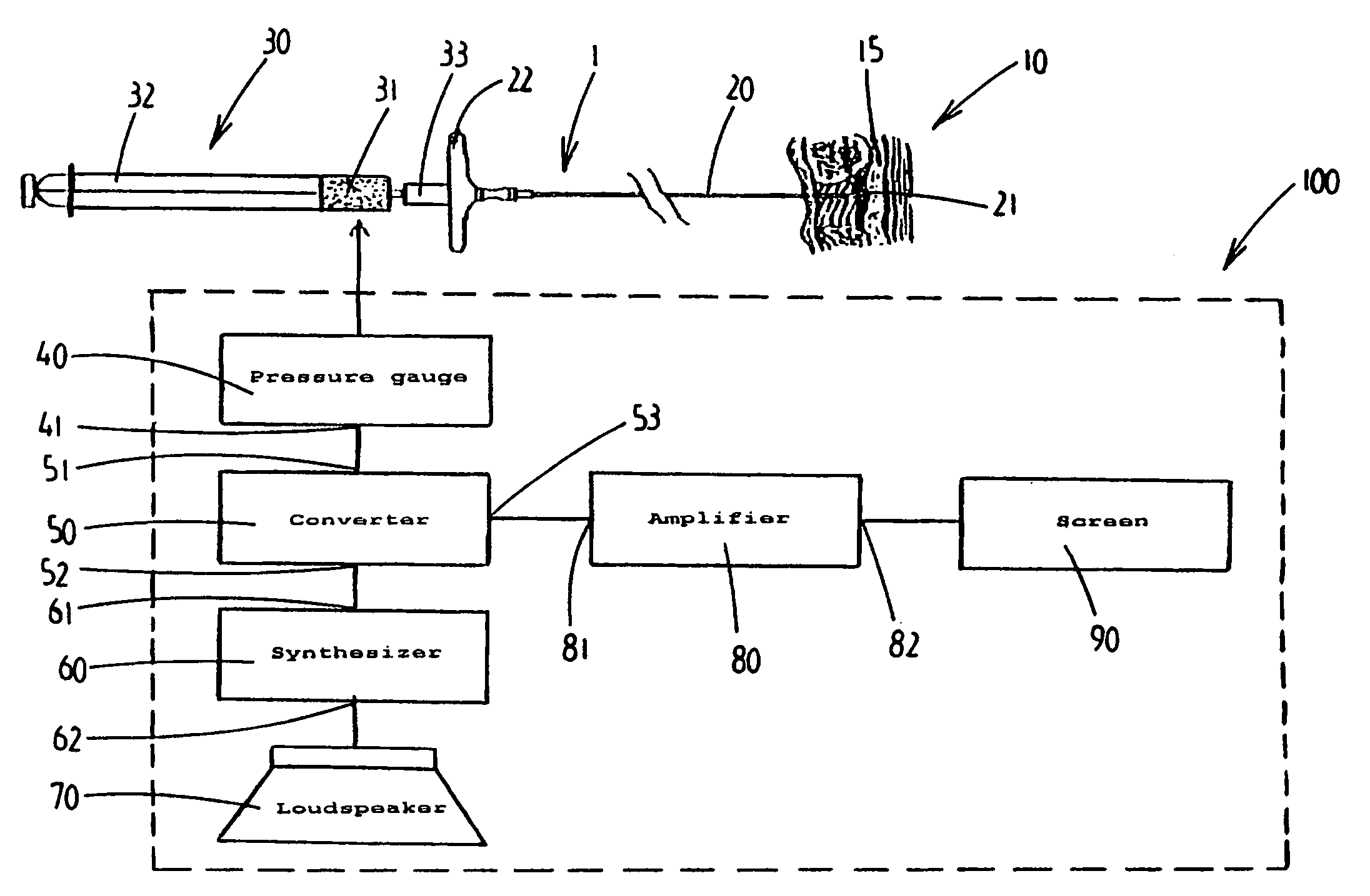
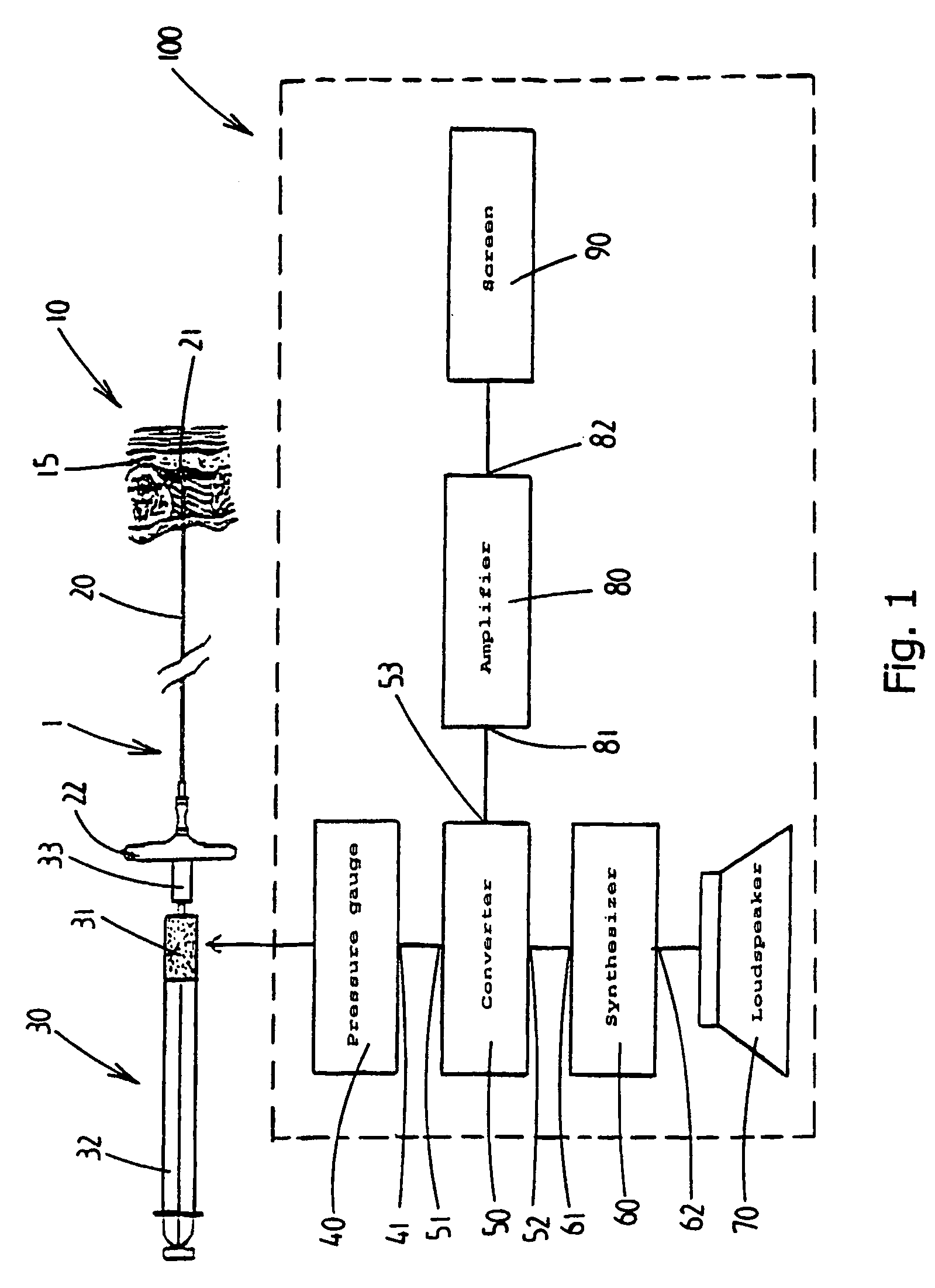
[0024]FIG. 1 shows a first preferred embodiment of the device according to the invention, which is denoted overall by reference numeral 1.

[0025]FIG. 1 shows one of the possible uses of the device 1, specifically its use for locating an anatomical cavity, in particular the epidural cavity, in a human body. A small section of a human body is illustrated in cross section in FIG. 1 and is denoted by reference numeral 10. The anatomical cavity or epidural cavity is denoted by reference numeral 15.

[0026]The device 1 comprises a hollow puncture needle 20 with a needle point 21. In the example shown in FIG. 1, the puncture needle 20 has been introduced part way into the body 10 and the needle point 21 is situated in the vicinity of the epidural cavity 15. The puncture needle 20 is provided with a handle 22, which can be held by the person who is handling the puncture needle 20, for example a physician. This handle 22 enables the user to exert a pushing or pulling force on the puncture needl...


PUM


Abstract

A device (1) is designed for locating a region which is situated in a body (10). The device has a fluid-filled reservoir (30) which is closed off in a sealed manner by a displaceable plunger (32) and is connected to a hollow puncture needle (20). To measure the pressure prevailing in the fluid, the device has a pressure gauge (40). A signal converter (50) is used to convert a continuous pressure-measurement signal provided by the pressure gauge (40) into a form which is suitable for further processing. A synthesizer (60) is designed to process the converted pressure-measurement signal into a continuous sound signal which is representative of the pressure. If, during a displacement of the puncture needle (20), a needle point (21) reaches the anatomical cavity (15), the result is a readily perceptible change in the sound signal. The device records the pressure-measurement signal over the course of time.

Description

CROSS-REFERENCE TO RELATED APPLICATIONS[0001]This application is the national stage filing under 35 U.S.C.§371 of PCT / NL02 / 00405, filed Jun. 20, 2002, which claims priority to NL 1018334, filed Jun. 20, 2001, which is incorporated herein by reference.FIELD OF THE INVENTION[0002]The present invention relates to a device and a method for locating an anatomical cavity in a body.BACKGROUND OF THE INVENTION[0003]Locating an anatomical cavity in a body, for example the body of a patient, is important, inter alia, for anaesthetics, in which it is often necessary for substances which have an anaesthetic action to be introduced into the anatomical cavity, such as for example the epidural cavity which is located in the vicinity of the spinal cord. To locate the anatomical cavity, it is generally known to use a hollow needle and a reservoir filled with an isotonic liquid or with a gas mixture, often an injection syringe with a displaceable plunger. In this case, the hollow needle is introduced...

Claims


Application Information

Patent Timeline
Patent Type & Authority Patents(United States)
IPC IPC(8): A61M31/00A61B5/03A61B17/34A61M19/00
CPCA61B5/032A61B17/3401A61B5/4896A61B5/4839A61B5/7415A61B5/03
Inventor LECHNER, TIMOTHEUS JOAN MARIE
Owner APAD OCTROOI
Learn More