
Acoustic nacelle inlet lip having composite construction and an integral electric ice protection heater disposed therein

a composite construction and electric ice heater technology, applied in ohmic resistance heating, air-flow influencers, transportation and packaging, etc., can solve the problems of affecting the quantity and flow path of intake air, damaging fan/rotor blades, other internal engine components,

Active Publication Date: 2011-04-12
THE BF GOODRICH CO +1
View PDF118 Cites 70 Cited by
  • Summary
  • Abstract
  • Description
  • Claims
  • Application Information

AI Technical Summary

Problems solved by technology

Accumulated ice can change the geometry of the inlet area between annular housing 1418 and fan blade spinner 1416, and can adversely affect the quantity and flow path of intake air.
In addition, pieces of ice may periodically break free from the nacelle 1420 and enter the engine 1450, potentially damaging fan / rotor blades 1460 and other internal engine components.
Engine nacelles also channel fan noise from the engines, which can be a prime source of aircraft noise.
First, a heating element that is externally mounted on a nacelle inlet lip may be susceptible to damage from impacts by objects striking the inlet lip.
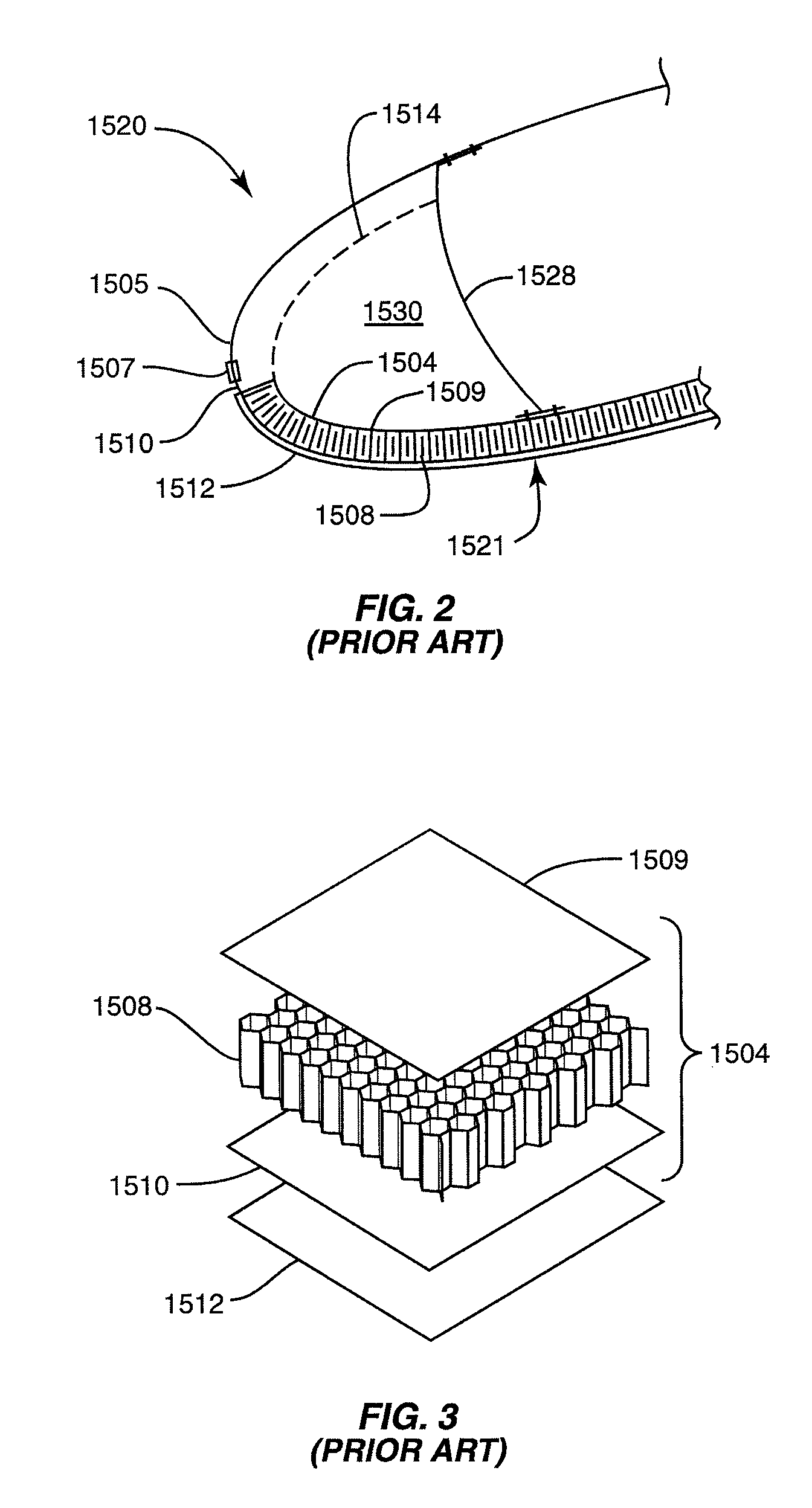
In addition, the adhesives used to bond porous, externally applied heating elements can at least partially block the acoustic openings in the heaters, thereby reducing the percentage of open area (“POA”) of the heaters, and decreasing the sound-attenuation capabilities of the inlet lip.

Method used


Image

  • Acoustic nacelle inlet lip having composite construction and an integral electric ice protection heater disposed therein
  • Acoustic nacelle inlet lip having composite construction and an integral electric ice protection heater disposed therein
  • Acoustic nacelle inlet lip having composite construction and an integral electric ice protection heater disposed therein

Examples


Embodiment Construction

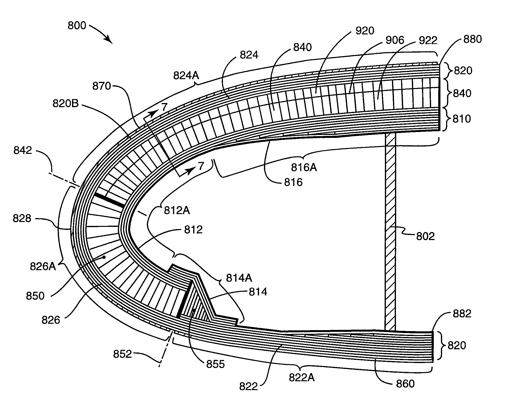
[0048]FIG. 5 shows a cross-section of a portion of one embodiment of a nacelle inlet lip 800 in accordance with the present invention. The inlet lip 800 includes an inner skin generally designated by reference numeral 810, and an outer skin generally designated by reference numeral 820. Both the inner skin 810 and outer skin 820 are connected to a bulkhead 802. The inner skin 810 and the outer inner skin 820 each comprises a multi-layer structure formed at least in part of a cured composite material, such as layers of graphite-epoxy fabric.

[0049]The inner skin 810 includes a plurality of sections, including a leading edge inner skin section 812 (extending along the region designated by reference numeral 812A in FIG. 5), a closeout section 814 (extending along the region designated by reference numeral 814A in FIG. 5), and a doubler section 816 (extending along the region designated by reference numeral 816A in FIG. 5).

[0050]The leading edge inner skin section 812 comprises a plurali...


PUM


Abstract

An engine nacelle inlet lip includes both acoustic treatment and electric heating for ice protection. The inlet lip has a composite outer skin and a composite inner skin, with the composite outer skin having at least one integrated heater element embedded in the composite material. An acoustic cellular core positioned between the outer and inner skin acts to attenuate fan noise from the engine. Covering the outer skin and overlying the acoustic core is a perforated erosion shield having a first set of openings that pass entirely thorough its thickness. The composite outer skin includes a second set of openings such that sound waves can pass from an inner barrel portion of the inlet lip through the erosion shield, outer skin, and heater element to the underlying acoustic cellular core.

Description

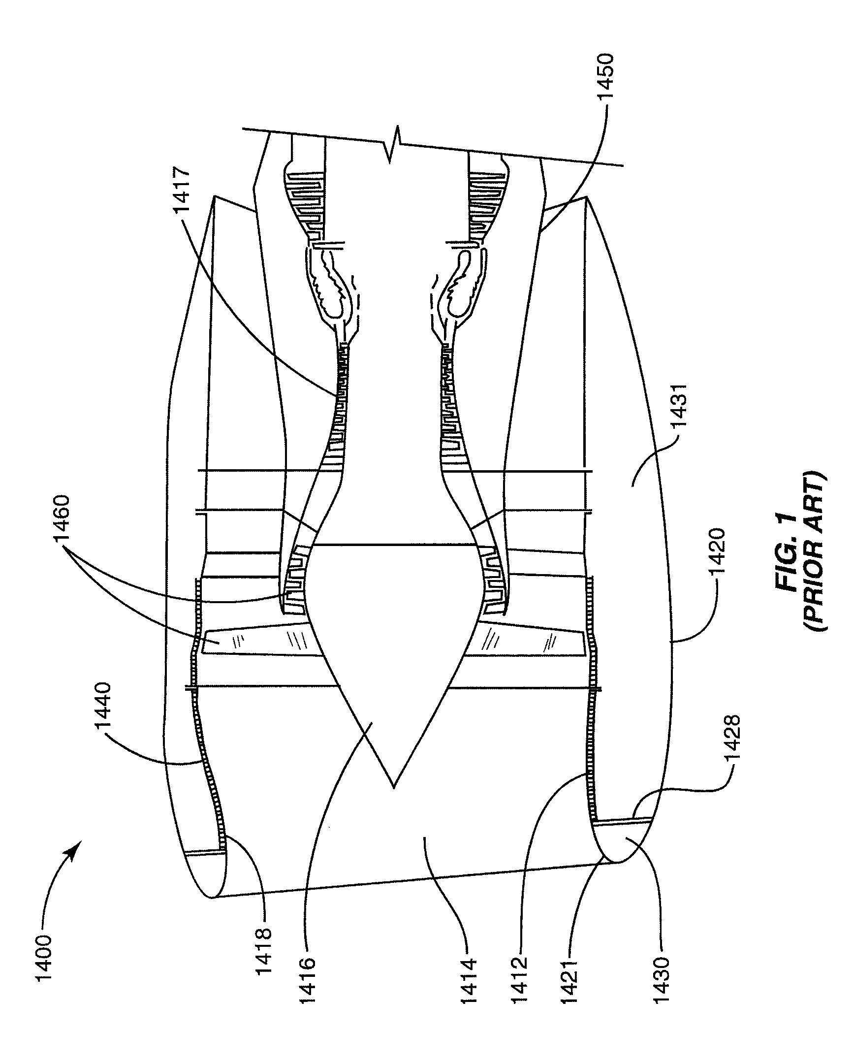
RELATED APPLICATIONS[0001]This application is a continuation-in-part of U.S. patent application Ser. No. 11 / 276,344, filed Feb. 24, 2006, now U.S. Pat. No. 7,291,815 and claims priority to U.S. provisional Application Ser. No. 60 / 791,967, filed Apr. 14, 2006. The entire contents of the aforementioned applications are hereby incorporated by reference.FIELD OF THE INVENTION[0002]The invention relates to ice protection systems for aircraft. More specifically, the invention relates to an aircraft equipped with a composite nacelle inlet lip having both an embedded electrical ice protection system and acoustic treatment.BACKGROUND OF THE INVENTION[0003]Aircraft engine nacelles are prone to ice buildup. FIG. 1 shows a schematic representation of a typical high-speed jet engine assembly 1400. Air enters through inlet section 1414, between fan blade spinner 1416 and the annular housing 1418, which constitutes the forward most section of the engine nacelle 1420, and includes nacelle inlet lip...

Claims


Application Information

Patent Timeline
Patent Type & Authority Patents(United States)
IPC IPC(8): H05B3/58B64C1/40B64D33/02
CPCB64D15/12B64D33/02H05B3/28B64D2033/0233B64D2033/0286B64D2033/0206
Inventor LAYLAND, MICHAEL JOHNBROWN, KEITH TOWERSHUBERT, CLAUDE MARCCHRISTY, DANIEL P.
Owner THE BF GOODRICH CO
Learn More