
Electron beam device

a technology of electron beam and beam beam, which is applied in the field of electron beam devices, can solve problems such as complicated control, and achieve the effect of decreasing the degree of operational flexibility of multi-biprism electron interferometers

Inactive Publication Date: 2011-04-12
HITACHI LTD
View PDF14 Cites 9 Cited by
  • Summary
  • Abstract
  • Description
  • Claims
  • Application Information

AI Technical Summary

Benefits of technology

The present invention is an electron beam device that includes an electron beam source, a condenser optical system, a specimen holder, and an imaging lens system. The device has two electron biprisms that are positioned upstream and downstream of the specimen in the traveling direction of the electron beam. The first electron biprism is placed in the optical axis of the electron beam device and the second electron biprism is positioned downstream of the first electron biprism and upstream of the imaging lens system. The invention allows for improved control of interferogram parameters and can be used with a variety of electron microscope configurations. It also allows for multiple imaging actions without the need for additional electromagnetic lenses and provides flexibility in the arrangement of the electron biprisms and electromagnetic lenses.

Problems solved by technology

Furthermore, a control mechanism for operating the added electromagnetic lens also needs to be newly added, which complicates control.

Method used


Image

  • Electron beam device
  • Electron beam device
  • Electron beam device

Examples


embodiment 6

sm Electron Interferometer with Another Lens Additionally Configured Upstream of Specimen

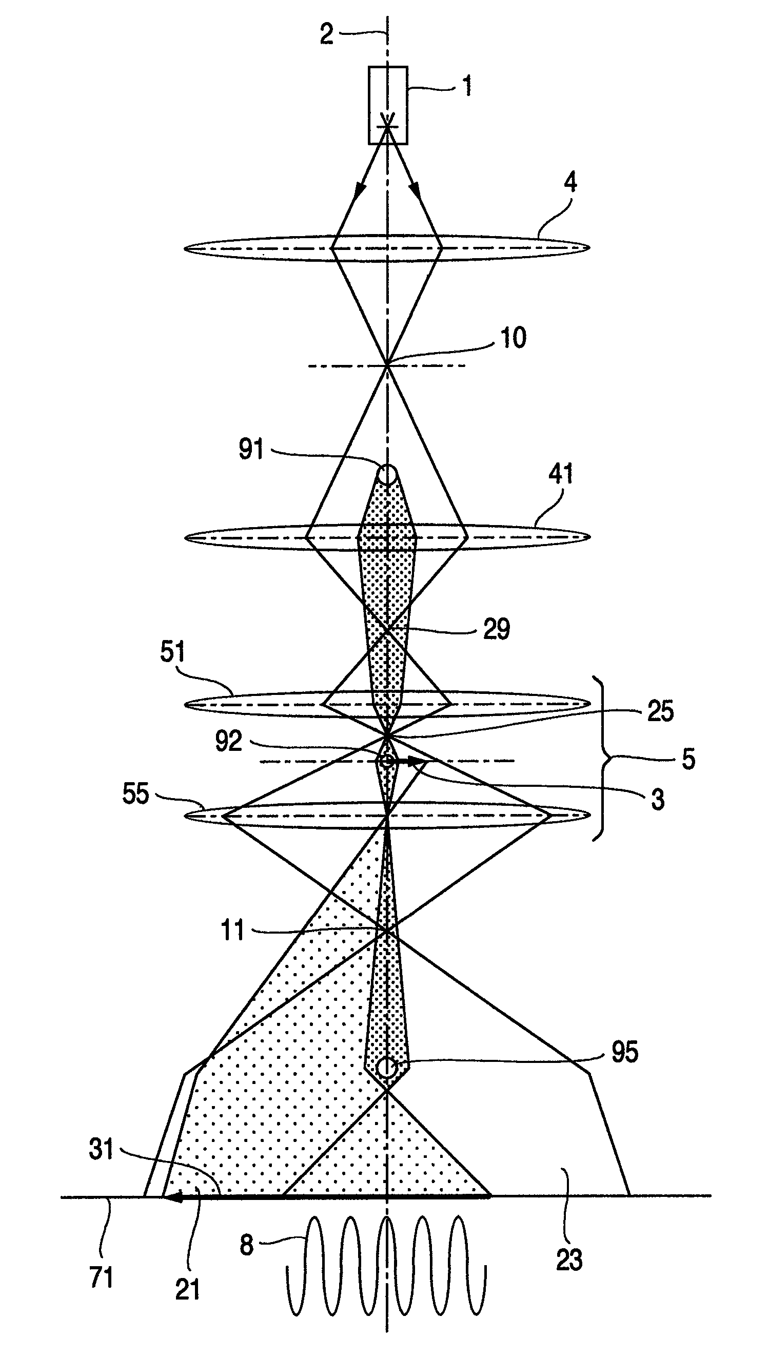
[0079]FIG. 15 shows a double-biprism electron interference optical system provided with an upper electron biprism 91 and an electromagnetic lens 41 operated in association with the electron biprism upstream of a specimen in the traveling direction of an electron beam. In the optical system including both the additionally configured electromagnetic lens 41 and the aforementioned pre-field lens 51, the central filament electrode 91 of the upper electron biprism is imaged on the specimen plane 3 (image 92). In the double-biprism electron interference optical system using the pre-field lens 51 of Embodiment 1, the magnification of the central filament electrode 91 of the upper electron biprism which has been imaged in a reduced size on the specimen is mainly determined depending on the position of the upper electron biprism and the size of the projected image decreases as the upper electron biprism ...


PUM


Abstract

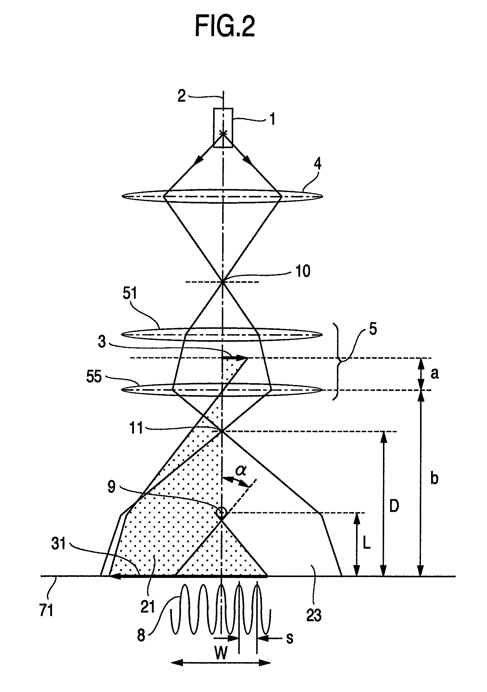
A multi-biprism electron interferometer is configured so as to arrange a plurality of biprisms in an imaging optical system of a specimen. An upper electron biprism is arranged upstream of the specimen in the traveling direction of the electron beam, and an image of the electron biprism is formed on the specimen (object plane) using an imaging action of a pre-field of the objective lens. A double-biprism interference optical system is constructed of a lower electron biprism disposed downstream of the objective lens up to the first image plane of the specimen.

Description

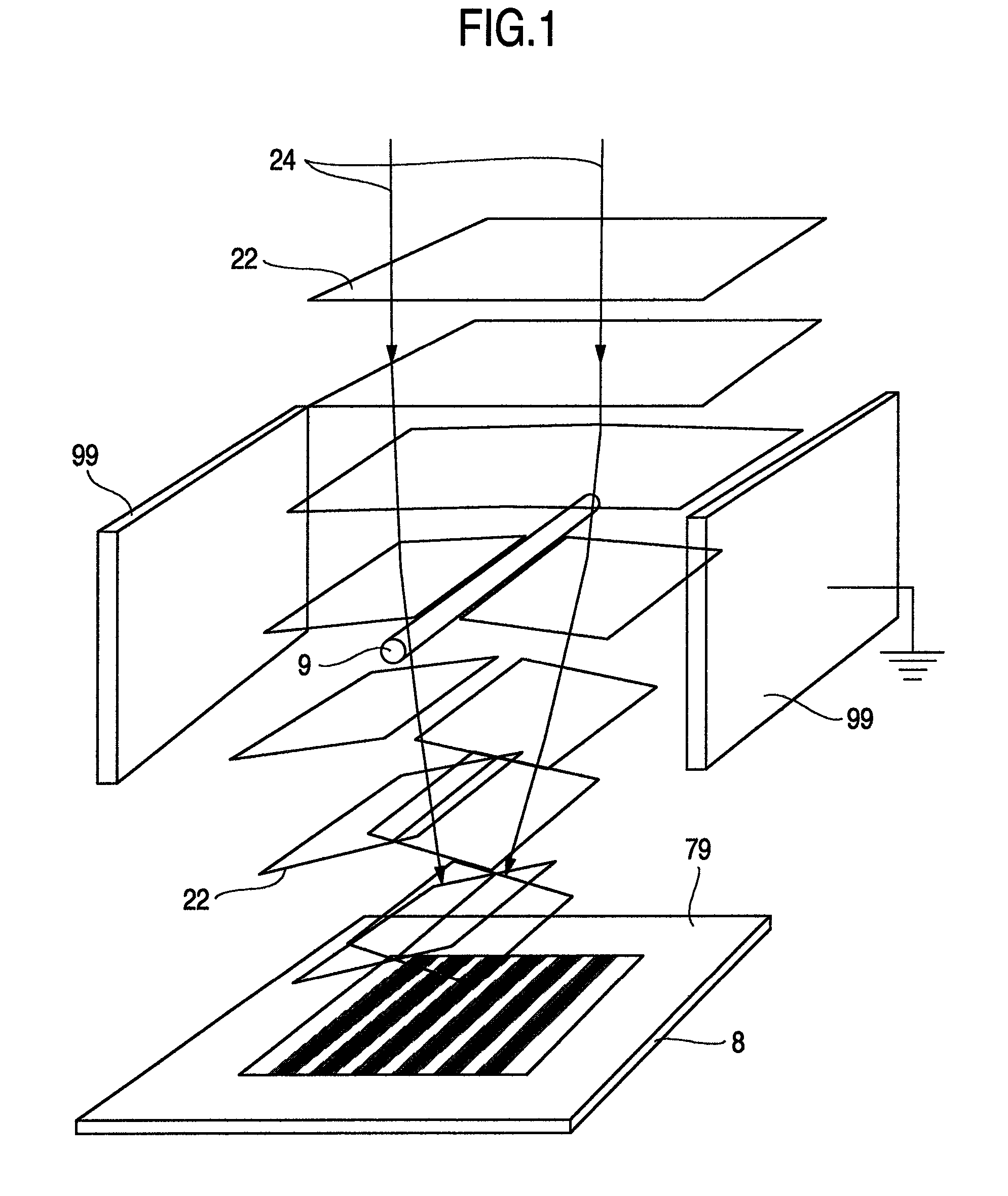
CLAIM OF PRIORITY[0001]The present application claims priority from Japanese application JP 2008-033948 filed on Feb. 15, 2008, the content of which is hereby incorporated by reference into this application.BACKGROUND OF THE INVENTION[0002]The present invention relates to an electron beam device making up an interferometer using an electron biprism.[0003]An electron biprism is used in explanations of the present specification. The electron biprism is a device in electron optics having the same action as that of Fresnel's biprism in optics and is classified into two types; electric field type and magnetic field type. Of the two, the one more widely used is the electric field type electron biprism and has such a shape as shown in FIG. 1. That is, the electric field type electron biprism is made up of a filament electrode 9 in the center and parallel flat plate type grounded electrodes 99 held so as to sandwich the electrode. For example, when a positive voltage is applied to the centr...

Claims


Application Information

Patent Timeline
Patent Type & Authority Patents(United States)
IPC IPC(8): H01J37/04
CPCH01J37/26H01J37/295H01J2237/0492H01J2237/2614H01J2237/1523H01J2237/228H01J2237/2588H01J2237/1514
Inventor HARADA, KENKASAI, HIROTO
Owner HITACHI LTD
Learn More