Carbon electrodes and electrochemical capacitors

a technology of electrochemical capacitors and carbon electrodes, which is applied in the direction of electrolytic capacitors, electrochemical generators, primary cells, etc., can solve the problems of increased resistance and performance loss

Inactive Publication Date: 2011-04-12
SMITH W NOVIS +1
View PDF8 Cites 19 Cited by
  • Summary
  • Abstract
  • Description
  • Claims
  • Application Information

AI Technical Summary

Benefits of technology

[0009]According to one embodiment of the invention there is provided improved carbon electrode...

Problems solved by technology

However as the voltage is pushed higher than 3.2 V a high leakage current with...

Method used


Image

  • Carbon electrodes and electrochemical capacitors
  • Carbon electrodes and electrochemical capacitors
  • Carbon electrodes and electrochemical capacitors

Examples


example 1

Preparation of Electrode

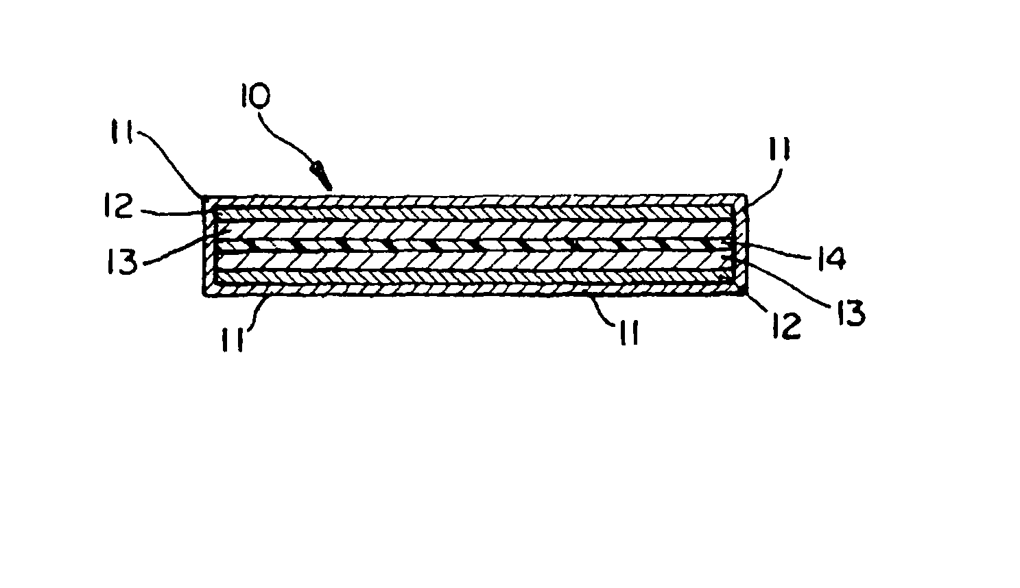
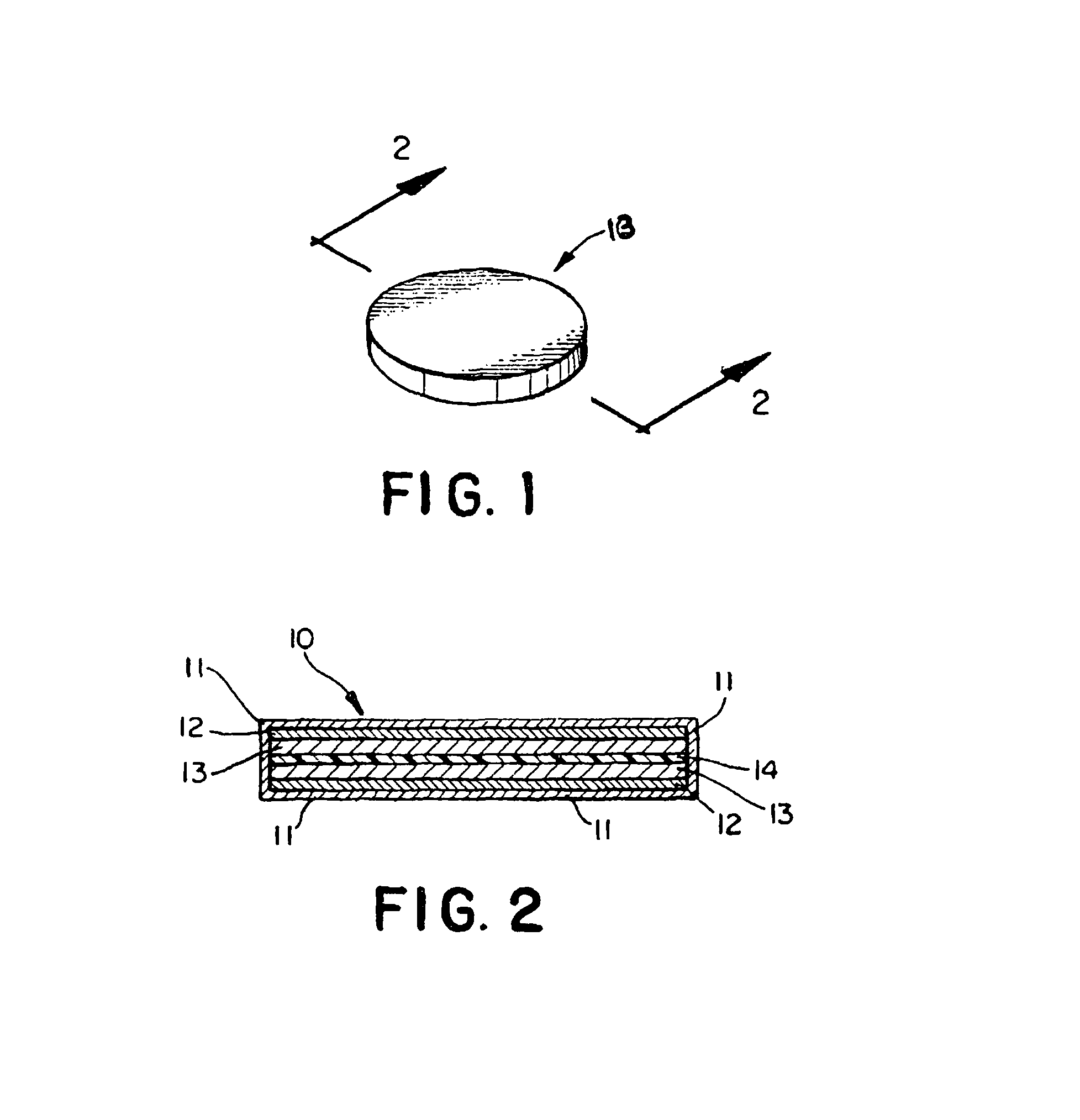
[0038]A. The carbon electrodes can be seen in FIGS. 1 and 2 prepared by forming an acetone slurry of 10% Kynar® resin and 90% carbon (0.5-10 microns) which have been treated to remove ash and silica. The mixture is cast onto a flat Teflon sheet and then the acetone is allowed to evaporate. The dried sheet is removed from the Teflon and ⅝″ circular electrodes are die cut and vacuum dried. The electrodes weigh about 0.01 gram and are 4 mil in thickness.

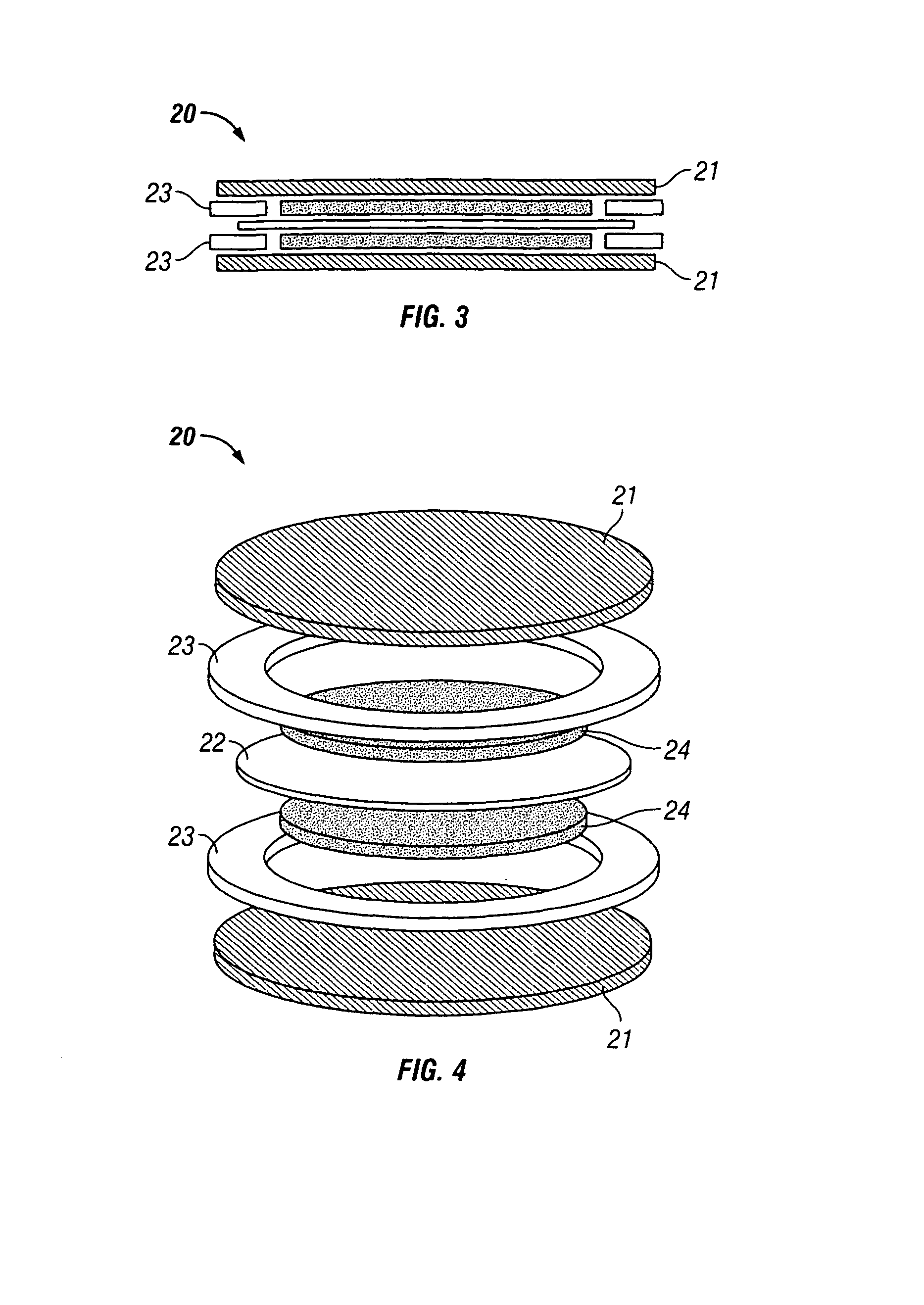
[0039]B. Alternatively, a carbon electrode (20) can be prepared as seen in FIGS. 3 and 4 by preparing the end plates (21) from a sheet of aluminum coated with a thin liquid conductive carbon dispersion and then baked. One dry, proper sized discs (21) are punched from the sheet and put on a roller to flatten the edges. Surlyn® rings (23) are then heat sealed to the end plates (21). The heat treated carbon is then made into a paste with 10% Surlyn binder and acetone. The paste is rolled into a sheet of about 4 mm o...

example 2

[0041]

Comparison of Capacitor Test Cells with DEDMABF4 in50 / 50 EC / PC Electrolyte Using Post-Treated Norit 30Carbon (0.008 g)CONCEN-RELATIVETRATION OFMACCORELECTROLYTEENERGYDEDM-BF4,LEAKAGECAPACITANCE(100 cycles)EC-PCESREIS(FARADS)mAh1.00 M 0.65VG0.50 (2.0 V)NAnone0.69 (4.1 V)0.291.5 M0.67VG0.56 (2.0 V)NAnone0.72 (4.1 V)0.352.0 M0.64VG0.37 (2.0 V)NAnone0.84 (4.1 V)0.343.0 M0.52VG0.72 (4.1 V)0.36noneThe greater molarity results in improved energy


PUM


Abstract

Carbon electrodes for a capacitor having conditioned carbon elements in combination with a high concentration of an electrolyte tetrafluoroborate salt and a non-aqueous aprotic solvent to provide an operational voltage up to 4.5V and capacitors used with the carbon electrodes.

Description

FIELD OF THE INVENTION[0001]The present invention relates to conditioned carbon for electrodes and electrochemical capacitors containing the electrodes. More particularly, there is provided a synergistic improvement when a capacitor utilizes a conditioned carbon for electrodes of the invention in combination with a non-aqueous non-acetonitrile electrolyte having a high concentration of an electrolyte salt which is a quaternary tetrafluoroborate salt.BACKGROUND OF THE INVENTION[0002]Activated carbon is the preferred material for use in preparing electrodes for carbon electrode capacitors. This activated carbon is prepared from a number of different sources such as coconut shells, wood, sugar, cellulosics and phenolic resins. After converting these materials to carbon under steam controlled conditions, the carbons are “activated” in a second step using steam or catalyzed with KOH, or carbon dioxide and KOH to increase the surface area to very high surface areas such as 1000 to 2400 m2...

Claims


Application Information

Patent Timeline
IPC IPC(8): H01G9/00
CPCH01G11/32H01G11/28Y02E60/13
Inventor SMITH, W. NOVISMCCLOSKEY, JOEL R.GORMLEY, JAMES J.
Owner SMITH W NOVIS
Why Eureka
Try Eureka