Terminal box for a solar cell panel

a solar cell panel and terminal box technology, applied in the direction of light radiation electric generators, coupling device connections, generators/motors, etc., can solve the problems of diode typically generating heat violently, diode may be broken, and the life of the diode may become considerably short, so as to achieve no breakage or shorten the life of the diode, and reduce the risk of damage to the terminal box. , the effect of reducing the risk of damag

Inactive Publication Date: 2011-04-19
ONAMBA CO LTD
View PDF15 Cites 8 Cited by
  • Summary
  • Abstract
  • Description
  • Claims
  • Application Information

AI Technical Summary

Benefits of technology

[0008]In the terminal box of the present invention, a Schottky barrier diode is used as the bypass diode, so that the heat generation at the time of the operation of the diode can be considerably restrained as compared with a PN diode that has been conventionally used. Also, since the terminal box of the present invention is directed to a crystalline silicon solar cell panel, the defects that the Schottky barrier diode has can be tolerated. Therefore, with the terminal box of the present invention, the temperature rise of the diode and the terminal box at the operation time of the diode can be prevented beforehand. Therefore, there will be no breakage or shortening of the lifetime of the diode, and there will be no drop off of the terminal box from the solar cell panel due to the deformation of the terminal box, whereby the safety and the reliability of the terminal box can be further enhanced.

Problems solved by technology

When the by pass diode actually performs this function, a large electric current flows in the forward direction of the diode, so that the diode typically generates heat violently.
This raises a possibility that the diode may be broken, or the lifetime of the diode may become considerably short, or the resin constituting the terminal box may be deformed with the heat generated by the diode to let the terminal box drop off from the solar cell panel.
However, since the output current of the crystalline silicon solar cell is larger by 30 times or more than that of the amorphous silicon solar cell, the amount of electric current that flows through the diode when the diode is operating, and subsequently the amount of generated heat, are considerably larger for the crystalline silicon solar cell than those of the amorphous silicon solar cell.
Therefore, in a terminal box that is used in a crystalline silicon solar cell, one cannot fully restrain the temperature rise of the diode simply by using the conventional general means that merely allows the generated heat of the diode to be dissipated with use of a heat-dissipating plate or the like.

Method used


Image

  • Terminal box for a solar cell panel
  • Terminal box for a solar cell panel
  • Terminal box for a solar cell panel

Examples


example 1

(1) Example 1

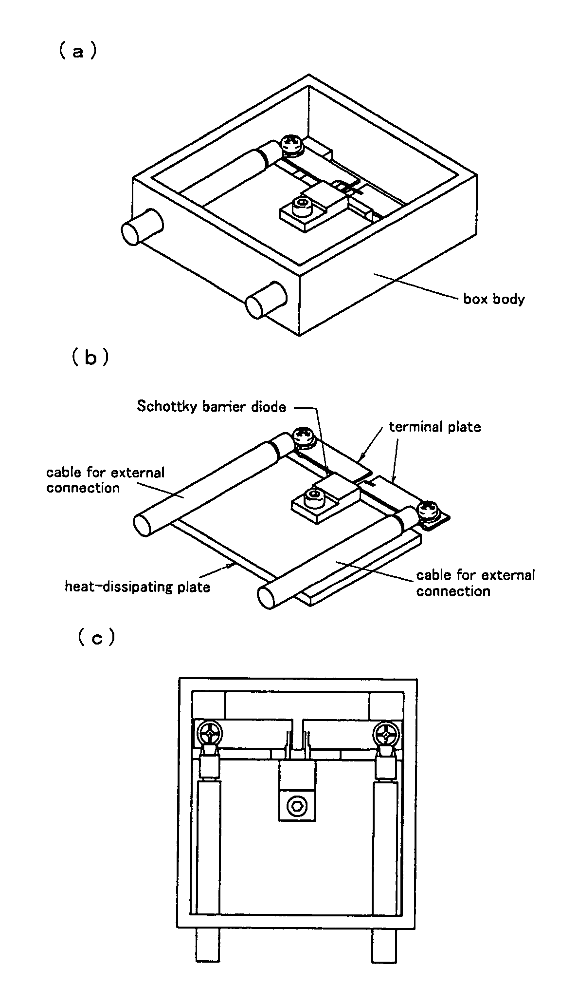
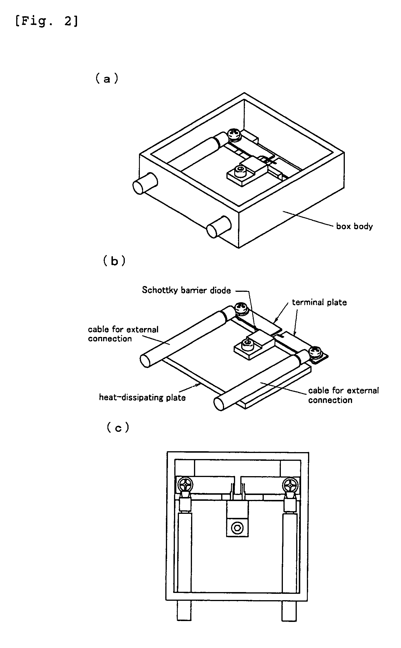
[0056]As a bypass diode, a Schottky barrier diode of 55V rating type shown in Table 2 was used to prepare a test sample having a structure as shown in FIG. 5. In the test sample of FIG. 5, two pairs of (four sheets of) terminal plates are placed in the inside of a box body made of resin, and three surface-mounting type Schottky barrier diodes are electrically connected thereto. Among the four sheets of terminal plates, the three sheets of terminal plates excluding the terminal plate on the right end are enlarged to be planarly larger than the usual dimension (See also the plan view of the inside of the box body shown in FIG. 6 for reference). In addition, three sheets of heat-dissipating plates are respectively mounted on the enlarged terminal plates.

example 2

(2) Example 2

[0057]A test sample was prepared in the same manner as in the Example 1 except that the diode was changed to a 55V rating low-leakage type Schottky barrier diode shown in Table 2 in the test sample shown in FIG. 5.

example 3

(3) Example 3

[0058]A test sample was prepared in the same manner as in the Example 1 except that the diode was changed to a 100V rating type Schottky barrier diode shown in Table 2 in the test sample shown in FIG. 5.


PUM


Abstract

A means for effectively preventing the temperature rise of the diode when the bypass diode is operating in a terminal box for a crystalline silicon solar cell panel is provided. The present invention is characterized in that, in the terminal box for a crystalline silicon solar cell panel, Schottky barrier diode is used as a bypass diode. Preferably, the forward-direction voltage drop of the Schottky barrier diode is the specific value or below at the specific junction temperature. Preferably, as a Schottky barrier diode, a package diode which is surface-mounting type or non-insulation type is used.

Description

TECHNICAL FIELD OF THE INVENTION[0001]The present invention relates to a terminal box for a crystalline silicon solar cell panel that can effectively prevent the temperature rise of the diodes and the terminal box by using a Schottky barrier diode as a bypass diode.BACKGROUND ART[0002]A terminal box for a solar cell panel is typically equipped with a bypass diode for short-circuiting the electric current generated by application of a reverse-direction voltage from one external-connection cable to the other external-connection cable when the electromotive force of the solar cell panel drops. When the by pass diode actually performs this function, a large electric current flows in the forward direction of the diode, so that the diode typically generates heat violently. This raises a possibility that the diode may be broken, or the lifetime of the diode may become considerably short, or the resin constituting the terminal box may be deformed with the heat generated by the diode to let ...

Claims


Application Information

Patent Timeline
Patent Type & Authority Patents(United States)
IPC IPC(8): H02N6/00
CPCH01L31/02021H02S40/345H02S40/34Y02E10/50
Inventor NAGAI, TSUYOSHIISHIDA, JUN
Owner ONAMBA CO LTD
Why Eureka
Try Eureka