Signal-driving system and shift register unit thereof

a technology of shift register and driving system, which is applied in the direction of digital storage, instruments, computing, etc., can solve the problems of the following shift register stage and the shift register circuit to be unable to opera

Active Publication Date: 2011-04-19
AU OPTRONICS CORP
View PDF13 Cites 6 Cited by
  • Summary
  • Abstract
  • Description
  • Claims
  • Application Information

AI Technical Summary

Benefits of technology

[0010]Therefore, to resolve the abovementioned drawbacks, a primary object of the present invention is to provide a signal-driving system, of which a shift register unit in each of multiple stages can avoid involvement of the gate pulse signal outputted from the other stage to preserve an independent manipulation of the system circuit.

Problems solved by technology

If the gate line and data line in the liquid crystal panel are shorted together by some defects, it would result in malfunction of the shift register circuit.
Thus, the similar problem also existed, that is, when the gate line and data line in the liquid crystal panel are shorted together by some defects, it would result in malfunction of the following shift registers stages.

Method used


Image

  • Signal-driving system and shift register unit thereof
  • Signal-driving system and shift register unit thereof
  • Signal-driving system and shift register unit thereof

Examples


Embodiment Construction

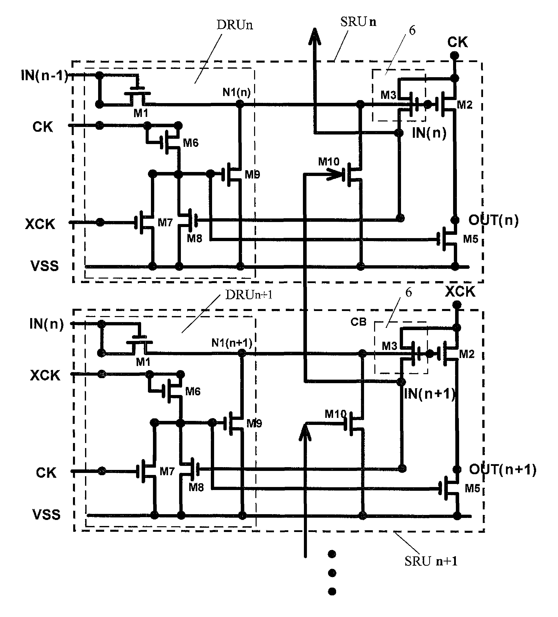
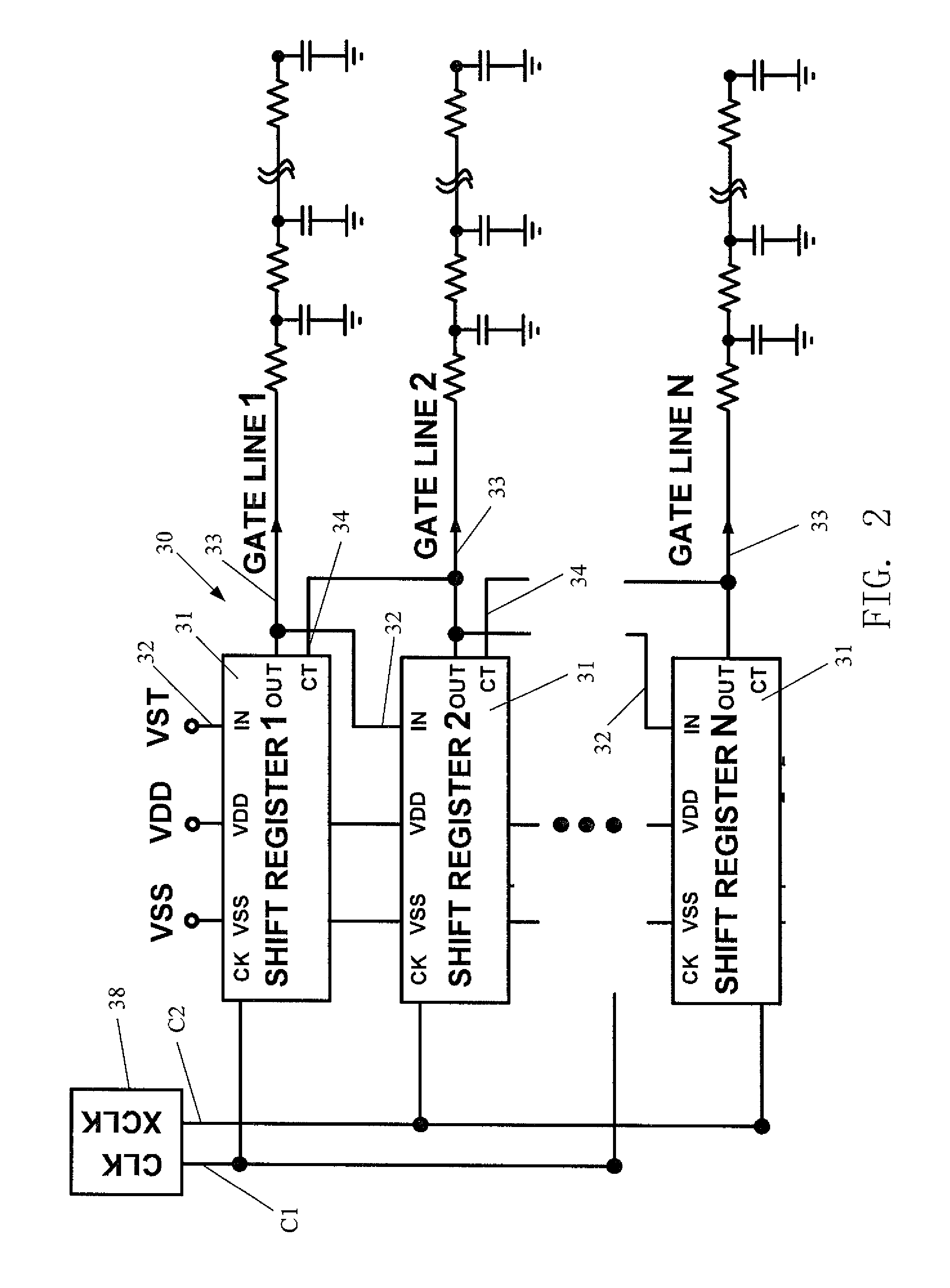
[0024]Please firstly refer to illustration of FIG. 5. A signal-driving system 50 according to a prefer embodiment of the present invention is introduced herein, which includes a multi-stage cascaded shift register units from ‘SRU1’ to ‘SRUn’. The shift register unit ‘SRU1˜n’ in each stage includes a shift register circuit ‘SRC1˜n’ and a carry buffer unit ‘CB1˜n’. Each of the shift register units ‘SRU1˜n’ outputs a gate pulse signal in turn, based on either a first clock signal ‘CK’ or a second clock signal ‘XCK’ in a special carrying clock cycle originated from a clock generator 56. Noted that the first clock signal ‘CK’ reveals an inverse phase relative to the second clock signal ‘XCK’ in this preferred embodiment.

[0025]Initially, after the shift register unit ‘SRU1’ in the first stage receives an initial scan pulse signal ‘VST’, the shift register unit ‘SRU1’ will output a gate pulse signal to a liquid crystal display (LCD) panel via a gate line “GATE LINE 1” for beginning of the ...


PUM


Abstract

A signal-driving system for constructing gate signals of liquid crystal display (LCD), includes a plural stage of cascaded shift register units. Each stage of shift register unit includes a first pull-up switch unit, which is turned on for outputting a gate pulse on an output of this stage, based on either the first clock signal or the second clock signal; a pull-up driving unit, which is used for providing a driving pulse via a node for driving the first pull-up switch unit; a first pull-down switch unit, which is turned on to connect the output to a low-level voltage source; a second pull-down switch unit, which is turned on to connect said node to the low-level voltage source; a carry buffer unit, which is used for providing a control pulse on the second pull-down switch unit of previous stage, based on either the first clock signal or the second clock signal, and thereby ensuring operation of each stage independent of gate pulse signals outputted from the other stages.

Description

BACKGROUND OF THE INVENTION[0001]1. Field of the Invention[0002]The present invention relates to a signal-driving system and shift register unit thereof, and more particularly to a signal-driving system having multi-stage shift register units, each of them operates independently of involvements of gate pulse signals outputted from the other stages.[0003]2. Description of the Prior Art[0004]As shown in FIG. 1, a schematic structure diagram regarding to a conventional liquid crystal display (LCD) 10 includes a set of driving circuits and a liquid crystal display panel 12 electrically connected to the driving circuits for controlling output signals of a plurality of pixel units 20 located in the liquid crystal display panel 12. Each three pixel units 20 indicating three primary colors, red, green and blue (RGB) is used to form a pixel and these pixels arrange as a matrix in the LCD 10. The driving circuits further include a gate driver 14, which is electrically connected with several t...

Claims


Application Information

Patent Timeline
Patent Type & Authority Patents(United States)
IPC IPC(8): G09G3/36
CPCG09G3/3648G09G3/3677G11C19/28G09G2320/0223G09G2300/0417
Inventor KUO, YU-JULAI, MING-SHENGCHENG, KUO-HSINGCHIEN, CHIH-YUAN
Owner AU OPTRONICS CORP
Why Eureka
Try Eureka