

Measuring device
- Summary
- Abstract
- Description
- Claims
- Application Information
AI Technical Summary
Benefits of technology
Problems solved by technology
Method used
Image

Examples
Embodiment Construction
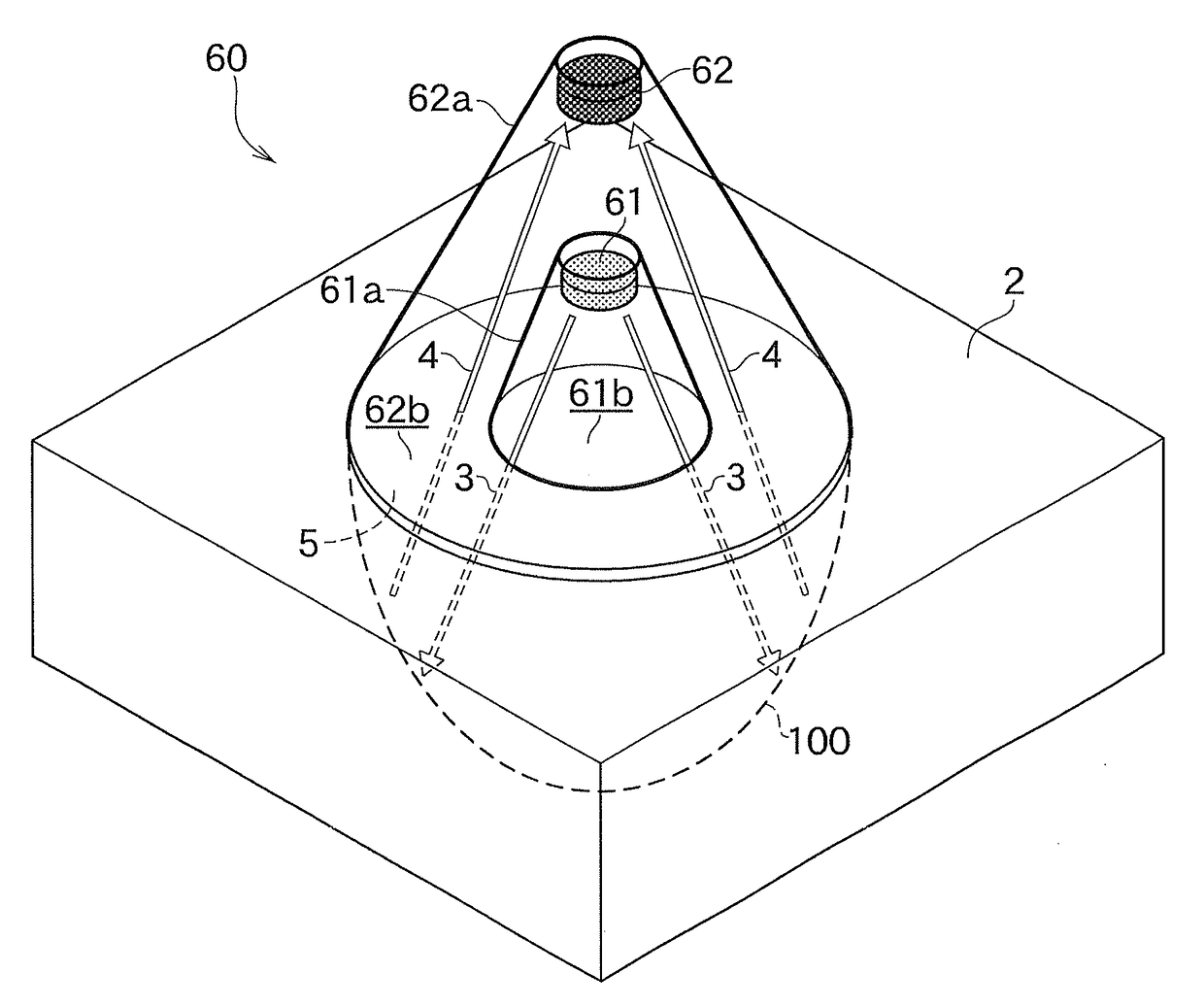
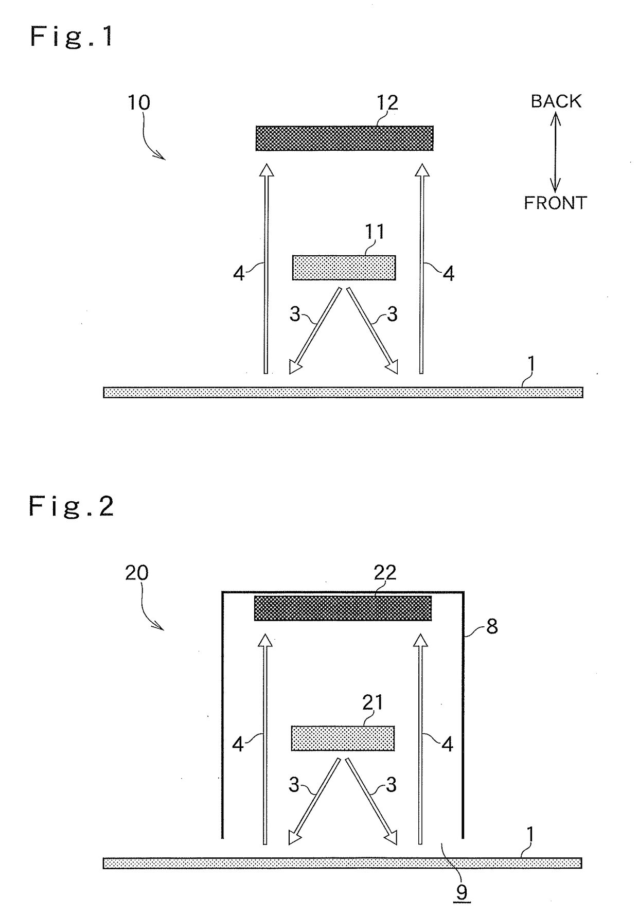
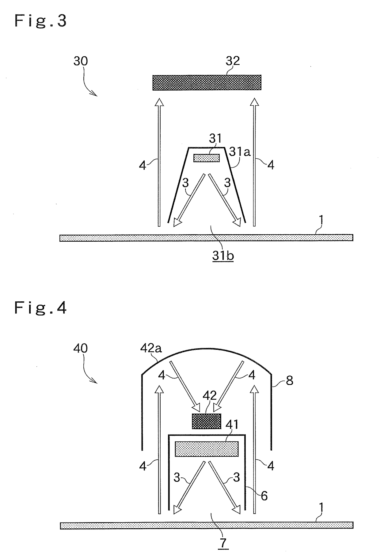
[0026]Measuring devices according to embodiments of the present invention are described below with reference to the drawings. The measuring devices are reflection-type measuring devices that measure backscattered waves in microwave application measurement. The measuring devices include a microwave transmitting unit and a microwave receiving unit, with the microwave receiving unit being disposed behind the microwave transmitting unit with respect to an object to be measured. Microwaves are transmitted in the direction of an object to be measured, and reflected waves from the object to be measured are measured. The measuring devices are used in level measurement and water content measurement. In the direction below, in FIG. 1, the direction in which microwaves are transmitted towards an object to be measured from the measuring device is defined as the front, and the direction in which the microwaves are reflected is defined as the back.
[0027]In a measuring device 10 according to a fir...
PUM
 Abstract
Description
Claims
Application Information