Optical sound track scanner system

a scanner and optical sound technology, applied in the field of optical sound scanner systems, can solve the problems of generating more noise, primary source of noise, and limited optical sound bandwidth, and achieve the effect of minimizing cost and effort and simplifying the process

Inactive Publication Date: 2011-04-19
LASER INTERFACE PHOTONICS
View PDF19 Cites 0 Cited by
  • Summary
  • Abstract
  • Description
  • Claims
  • Application Information

AI Technical Summary

Benefits of technology

[0063]It is an important advantage of the present invention that by proper signal processing, e.g. by proper adjustment of the above-mentioned channel characteristics, threshold level and / or trigger levels, of the detector signal, the recorded signal is obtained directly from scanning of the optical sound track on the negative film, i.e. without the need for making a contact print of the negative film, simplifying the process and minimizing cost and effort.
that by proper signal processing, e.g. by proper adjustment of the above-mentioned channel characteristics, threshold level and / or trigger levels, of the detector signal, the recorded signal is obtained directly from scanning of the optical sound track on the negative film, i.e. without the need for making a contact print of the negative film, simplifying the process and minimizing cost and effort.

Problems solved by technology

Regardless of the technique employed, the bandwidth of optical sound has traditionally been limited to 9-10 kHz particularly when mechanical shutters are used.
A primary source of noise is dust, dirt, debris and scratches on the film.
As a result more noise is generated as the open or transparent areas of the sound track increase.
This problem is particularly severe for optical sound track negatives.
On negatives, the transparent area on the sound track is largest when the sound signal level is low, and since low-level signals are not nearly as effective as high-level signals in masking noise, the resulting signal-to-noise level may be unacceptable.
In particular old movies, which were recorded without modern noise-reduction systems, suffer from this.

Method used


Image

  • Optical sound track scanner system
  • Optical sound track scanner system
  • Optical sound track scanner system

Examples


Embodiment Construction

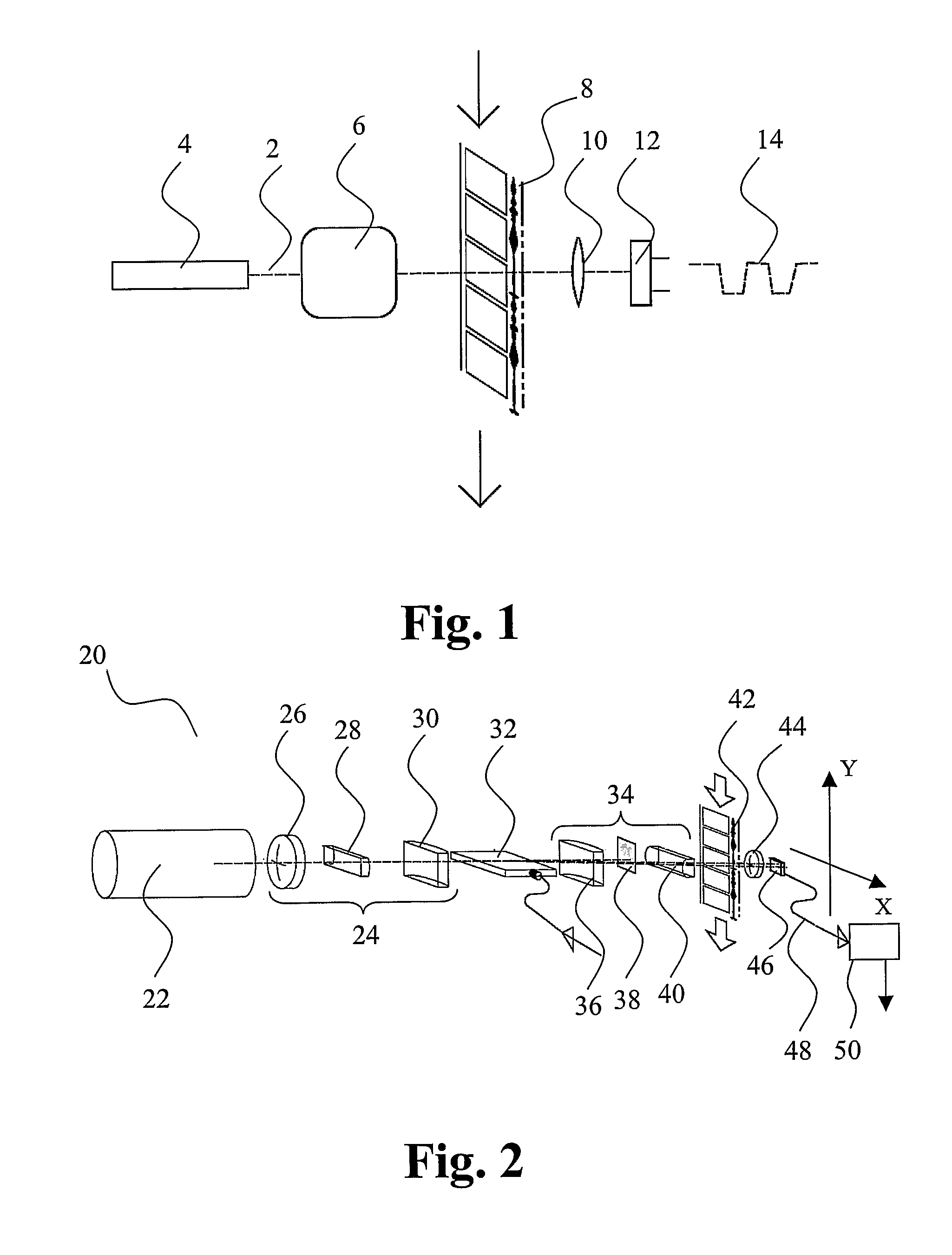
[0079]The principle of operation of the optical scanner system is schematically illustrated in FIG. 1. A light beam 2 is emitted from a laser 4 and a scanner 6 moves the light beam in a regular pattern across the film sound track 8 in a direction perpendicular to the direction of film movement indicated by the arrow 1. A lens 10 collects the light after transmission through the film onto a detector 12, which generates an electrical signal 14 that goes low when the light beam is blocked and high when the light beam is transmitted through the film. The system produces time-slices of the sound track in the form of a pulse-width modulated signal. The pulse edges are subsequently transformed by an electronic gate and trigger circuit (not shown) into clean pulses, which are subsequently demodulated and filtered into sound. Alternatively, the detector output signal may be digitised for further digital signal processing.

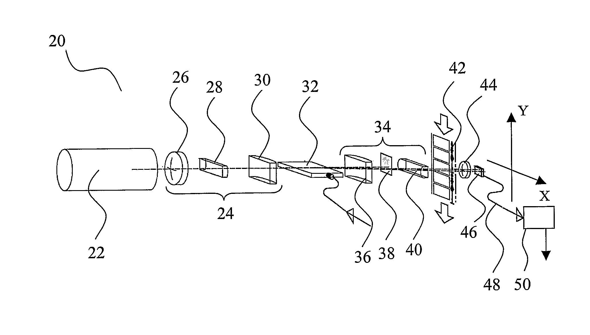
[0080]FIG. 2 shows an embodiment of the present invention employing an ...


PUM

PropertyMeasurementUnit
scanning frequencyaaaaaaaaaa
diameteraaaaaaaaaa
diameteraaaaaaaaaa

Abstract

The present invention relates to an optical scanner system for scanning of an optical sound track with a beam of light, comprising a light emitter for emission of a light beam, a device for scanning the light beam across an optical sound track, the light beam forming a scanning spot on the optical sound track, an optical detector for detection of the light beam upon interaction of the light beam with the optical sound track and generating an electronic signal representing the sound recorded in the optical sound track.

Description

CROSS REFERENCE TO RELATED APPLICATIONS[0001]This is the U.S. national phase application based on PCT application No. DK2005 / 000441 filed Jun. 28, 2005, which is based on Danish Application PA 2004 01024, filed Jun. 29, 2004, and U.S. Provisional Application Ser. No. 60 / 521,769, filed Jul. 1, 2004, the entire contents of all of which is hereby incorporated by reference.FIELD OF THE INVENTION[0002]The present invention relates to an improved optical scanner system for scanning of an optical sound track with a beam of light.BACKGROUND OF THE INVENTION[0003]Optical sound recording was invented in the beginning of the 20'th century. The sound is recorded by optical means on the film together with the pictures forming the movie. The recorded optical sound track consists of one or two narrow tracks extending along one of the sides of the film next to the sequence of picture frames. The optical sound track may be either intensity or width modulated, the modulation forming an analogue repre...

Claims


Application Information

Patent Timeline
Patent Type & Authority Patents(United States)
IPC IPC(8): G11B7/00G11B7/003
CPCG11B7/0032
Inventor LAUSEN, HENRIK
Owner LASER INTERFACE PHOTONICS
Why Eureka
Try Eureka