Wind turbine with rotor blades equipped with winglets and blades for such rotor

a technology of wind turbines and rotor blades, which is applied in the direction of propellers, propulsive elements, water-acting propulsive elements, etc., can solve the problems of reducing the lift coefficient at the tip section of the wing, causing drag and aerodynamic noise, and causing the tip vortex to rise, so as to reduce the adverse tip effect on the lift coefficient, the effect of increasing the performance of the part and reducing the adverse tip

Inactive Publication Date: 2011-04-26
VESTAS WIND SYST AS
View PDF13 Cites 41 Cited by
  • Summary
  • Abstract
  • Description
  • Claims
  • Application Information

AI Technical Summary

Benefits of technology

[0017]The advantages discussed above of the application of winglets on wind turbine blades have lead to design trend where the blade part extending from the hub and to the tip end of the blades immediately adjacent the winglet, i.e. at the winglet root, is designed as the inner part of a longer wind turbine blade because the presence of the winglet reduces the adverse tip effects on the lift coefficient at the outer part of the blade near the tip and a higher performance of that part of the blade may be achieved, which is particularly interesting because this part sweeps a large section of the total area swept by the rotor. This design leads to relatively large chord lengths at the outer part of the blade, i.e. the outer about 5% of the complete rotor radius.
[0018]It is an object of the present invention to provide an improved design of a wind turbine blade with a winglet that results in an improved performance of the wind turbine with respect to yearly production and preferably also reduced noise emission.
[0019]It has been found by the present invention that an optimisation of the performance of the wind turbine may be achieved by designing the outer part of the blade much more slim, i.e. with a shorter chord length designed within a narrow band of values defined with respect to the length of the winglet, i.e. the extension in the direction transverse to the longitudinal direction of the blade. The reduction in chord length has shown to reduce the actual drag more than the reduction in lift and results in an improved performance. Thus, the present invention relates to a wind turbine comprising a rotor with wind turbine blades each having a root end connected to a hub of the wind turbine and a tip end, the tip end of each of which being equipped with a winglet extending a distance in a direction perpendicularly to a longitudinal direction of the blade, wherein the combined radius specific solidity (Solr) of the rotor at the tip end of the blades immediately adjacent the winglet is 0.085 times the extension of the winglet divided by the radius of the rotor, plus a value within the range of 0.0012 and 0.0048. However, for an optimum effect of the winglet, the inventor's studies indicates that said value preferably is within the range of 0.0016 and 0.0042, and most preferred within the range of 0.0024 and 0.0040. The extension of the winglet and the radius of the rotor are taken in absolute values, so that their ratio, i.e. the extension of the winglet divided by the radius of the rotor, will be a fraction, typically in the order of 0.01 to 0.04. Thus, an example of a typical calculation of the combined radius specific solidity (Solr) of the rotor at the tip end of the blades immediately adjacent the winglet is for a blade where the ratio of the winglet extension and the rotor radius is 0.025 and said value is selected as a medial value of the last mentioned range: (0.085 times 0.025)+0.0032=0.0053.
[0036]The extension of the winglet may with the present invention exceed the commonly applied 1.2% to 1.5% of the rotor radius with improved performance of the wind turbine. Thus, the winglet extends preferably in the range of 0.5% to 5% of the radius R of the rotor, and most preferred in the range of 2% to 4% of the radius.
[0039]The winglet may extend to the pressure side, which is the most common in order to avoid interference with the wind turbine tower, or the winglet may extend to the pressure side as well as to the suction side of the blade. However, it is preferred that the winglets extend said distance (Xheight) to the suction side of the blades of the rotor as it in combination with the present invention has shown to provide an improved performance of the wind turbine.

Problems solved by technology

It has for a number of years been common practice in air craft wing design to arrange different types of winglets or other means at the wing tip for reducing or preventing the spanwise flow of air from the pressure (lower) side of the wing profile to the suction (upper) side of the profile around the tip, which results in the creation of the tip vortex and a decreased lift coefficient at the tip section of the wing, mainly due to the reduced suction at the suction side.
At the trailing edge, the merging of these two flows having different directions generates the vorticity that is shed from a finite wing and is the origin of induced drag as well as aerodynamic noise.
Unfortunately, to be effective, the endplate must be so large that the increase in wetted area drag far outweighs any drag reduction.

Method used


Image

  • Wind turbine with rotor blades equipped with winglets and blades for such rotor
  • Wind turbine with rotor blades equipped with winglets and blades for such rotor
  • Wind turbine with rotor blades equipped with winglets and blades for such rotor

Examples


Embodiment Construction

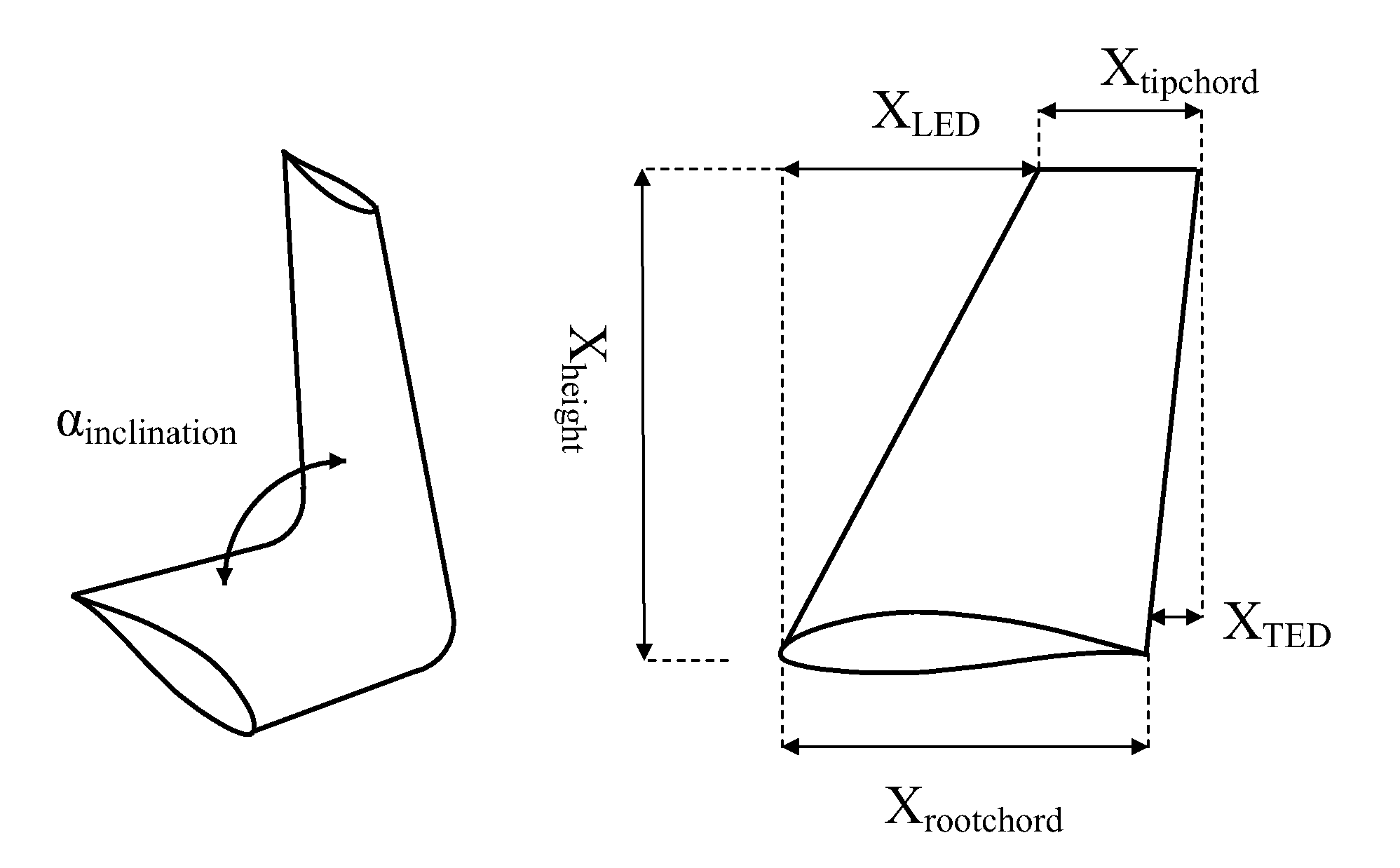
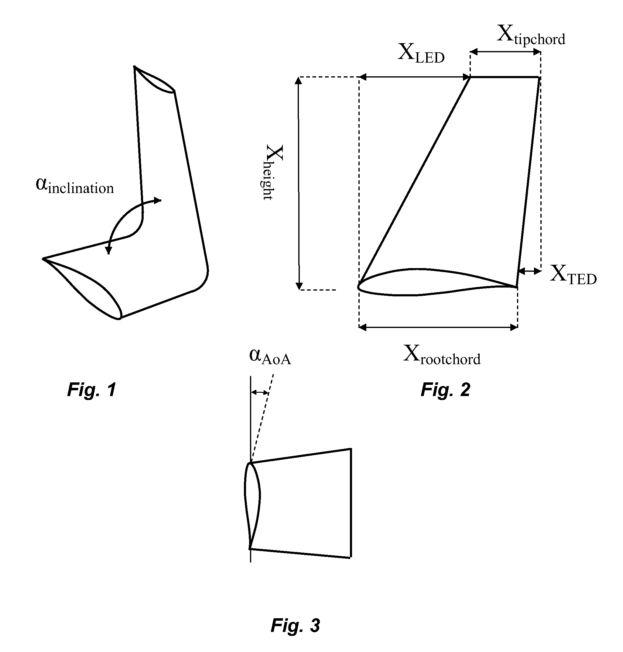
[0052]In FIG. 1, the tip end of a blade is shown as seen in perspective with the winglet pointing upwards, and the inclination of the winglet to the blade is shown as the winglet inclination angle to blade, αinclination, defined as the angle between the main wing centre line and the winglet centre line.

[0053]In FIG. 2 the tip end of a blade is shown as seen from the end thereof, i.e. the blade itself extends away from the viewer of FIG. 3. The winglet height, Xheight, is defined as the distance from the main wing chord line at the very tip to the chord line of the very tip of the winglet. The winglet root chord, Xrootchord, is defined as the distance from the leading edge to the trailing edge of the main wing at the very tip where the winglet is attached. The winglet tip chord, Xtipchord, is defined as the distance from the leading edge to the trailing edge of the winglet at the very tip of the winglet. The winglet leading edge displacement, XLED, is defined as the distance from the...


PUM


Abstract

A wind turbine includes a rotor with wind turbine blades each having a root end connected to a hub of the wind turbine and a tip end, the tip end of each of which being equipped with a winglet extending a distance in a direction perpendicularly to a longitudinal direction of the blade. A new and much more slim design of the outer part of the wind turbine blade is disclosed, i.e. with a shorter chord length designed within a narrow band of values defined with respect to the length of the winglet, i.e. the extension in the direction transverse to the longitudinal direction of the blade.

Description

CROSS-REFERENCE TO RELATED APPLICATIONS[0001]The present application is a continuation of pending International patent application PCT / DK2007 / 000559 filed on Dec. 20, 2007 which designates the United States and claims priority from Danish patent application PA 2007 01142 filed Aug. 10, 2007 and Danish patent application PA 2006 01705 filed Dec. 22, 2006, the content of which is incorporated herein by reference.FIELD OF THE INVENTION[0002]The present invention relates to a wind turbine having a rotor with wind turbine blades equipped with winglets and having a particular airfoil design to improve the performance of the wind turbineBACKGROUND OF THE INVENTION[0003]It has for a number of years been common practice in air craft wing design to arrange different types of winglets or other means at the wing tip for reducing or preventing the spanwise flow of air from the pressure (lower) side of the wing profile to the suction (upper) side of the profile around the tip, which results in th...

Claims


Application Information

Patent Timeline
Patent Type & Authority Patents(United States)
IPC IPC(8): F03D1/02
CPCF03D1/06F03D1/0608F03D11/00Y10S416/02Y02E10/721Y02E10/722F05B2240/30F05B2240/307Y02E10/72
Inventor GODSK, KRISTIAN BALSCHMIDTNIELSEN, THOMAS STEINICHE BJERTRUP
Owner VESTAS WIND SYST AS
Why Eureka
Try Eureka