Eureka AIR delivers breakthrough ideas for toughest innovation challenges, trusted by R&D personnel around the world.

Thermal energy transfer circuit system

a technology of thermal energy transfer circuit and thermal energy, which is applied in the direction of thermoelectric devices with peltier/seeback effect, basic electric elements, electric apparatus, etc., can solve the problems of increasing energy consumption, increasing energy consumption, and the technique of actively generated thermal energy recycling without additional use of thermal or electric energy is not yet completed, so as to save energy and reduce noise. the effect of

Active Publication Date: 2011-04-26
MEIDENSHA ELECTRIC MFG CO LTD +1
View PDF15 Cites 1 Cited by
  • Summary
  • Abstract
  • Description
  • Claims
  • Application Information

AI Technical Summary

Problems solved by technology

This causes an increase in energy consumption, and noises generated in such cooling device, and thereby causes problems.
The technique to recycle actively generated thermal energy without additional use of thermal or electric energy is not yet completed.
Moreover, the noises generated in cooling devices, etc. are not yet reduced sufficiently.
Although thermal energy exists inexhaustibly in the natural world as described above, the technique to take out the thermal energy in the form of electric energy or chemical energy is still in an initial stage of development far from practical use.
Due to difference in the number of free electrons in the two conductors, electrons move between the two conductors, resulting in a potential difference between the two conductors.
Accordingly, the heating portion and the cooling portion interfere with one another in the Seebeck element, while the heat-absorbing portion and the heat-generating portion interfere with one another in the Peltier element.
Therefore, it is impractical to construct large-scale energy conversion equipment with such Peltier element and Seebeck element, because physical restriction is imposed by the place where the equipment is disposed.
According to patent document 1, a circuit system constructed with the Seebeck element or the Peltier element is limited to a system including an external power supply, and used in limited forms.
When the conventional technique as disclosed in patent document 1 is proposed, the use of energy with the Peltier element and the Seebeck element is unidirectional.
For example, there is no technical teaching of constructing a recycling system to recycle energy once converted into thermal form, foreclosing the associated external power supply, and reducing the accompanying noises in parallel.
This is a major required challenge in developing the technique to use thermal energy in the future.

Method used


Image

  • Thermal energy transfer circuit system
  • Thermal energy transfer circuit system
  • Thermal energy transfer circuit system

Examples


second embodiment

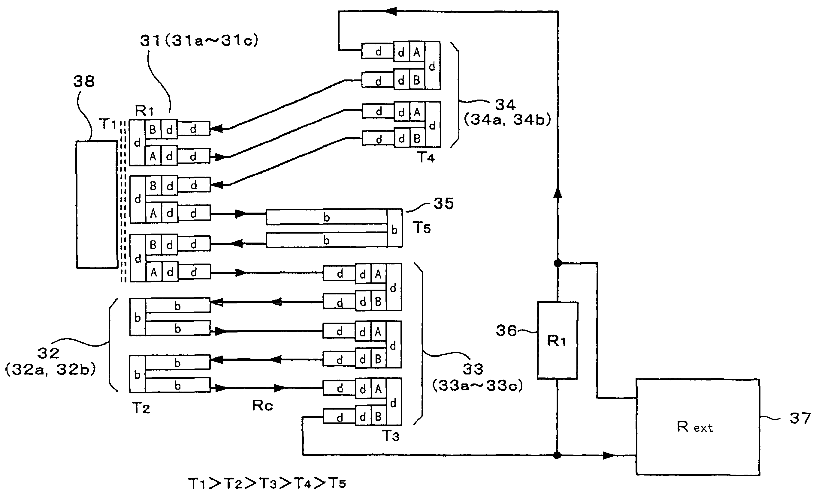
[0064]Next, the present invention is described with reference to FIG. 4. FIG. 4 is a schematic diagram showing a system for utilizing a thermal energy resource, converting it into electric energy, and supplying it to an external load circuit 37, i.e. a thermal energy resource to electric energy resource conversion and supply system.

[0065]As shown in FIG. 4, in the thermal energy resource to electric energy resource conversion and supply system, one or more thermoelectric conversion elements or conductive coupling members are disposed in five different temperature environments. Thermal energy of an external temperature T1 is supplied from an external heat source 38 that exists in the natural world or made artificially, to a joining member d that joins together a first conductive member A and a second conductive member B of each of thermoelectric conversion elements 31a to 31c constituting a first thermoelectric conversion element group 31. Thus, the first thermoelectric conversion el...

first embodiment

[0078]The application shown in FIG. 6 differs from the first embodiment shown in FIG. 4 in that the water electrolyzer 39 is provided in the position where the conductive coupling member 35 is disposed in FIG. 4.

[0079]In the conversion to chemical energy resource and storage system of FIG. 6, the first conductive member A of the thermoelectric conversion element 34a is connected to a hydrogen-generating electrode 39a of the water electrolyzer 39, while the second conductive member B of the thermoelectric conversion element 33c is connected to an oxygen-generating electrode 39b of the water electrolyzer.

[0080]The thermoelectric conversion elements 34a and 34b are cascaded with the thermoelectric conversion elements 31a and 31b, as in the example of FIG. 4. The first conductive member A of the thermoelectric conversion element 31b is connected to the oxygen-generating electrode 39b of the water electrolyzer 39 as described above. The hydrogen-generating electrode 39a of the water elec...


PUM


Abstract

A first conductive member and a second conductive member having different Seebeck coefficients are joined together by a joining member to form a plurality of thermoelectric conversion elements, and these thermoelectric conversion elements are disposed in at least two different temperature environments. The first conductive members of respective thermoelectric conversion elements or the second conductive members thereof are connected to each other by an electric wiring to form a direct energy conversion electric circuit system, and electric potential energy is picked up from an arbitrary portion on this electric wiring. Accordingly, the direct energy conversion electric circuit system from thermal energy to electric energy is formed. A water electrolyzer is disposed in the passage of the circuit system in which the first conductive members or second conductive members having connected respective thermoelectric conversion elements are connected to thereby able to convert thermal energy into chemical energy and sore it.

Description

TECHNICAL FIELD[0001]The present invention relates to a system with no external power supply for utilization of a thermal source exhausted or generated purely in the global environment, and conversion to electric energy or chemical energy. For example, the present invention relates to thermal energy existing in any section, space or region (hereinafter referred to as “space, etc.”) of a building, an object, etc. whose temperature is high under the influence of an external heat originating from electrical devices, combustion devices, their related devices, sunlight, geothermal heat, etc., and relates to a thermal energy transfer circuit system for transferring such thermal energy to a remote place distant from the space, etc., and to a system for converting such thermal energy directly to electric energy and supplying it.[0002]Moreover, the present invention relates to a conversion to chemical energy resource and storage system for converting thermal energy to chemical energy, and st...

Claims


Application Information

Patent Timeline
Patent Type & Authority Patents(United States)
IPC IPC(8): H01L35/28
CPCH01L35/32H01L35/30H10N10/17H10N10/13
Inventor KONDOH, YOSHIOMI
Owner MEIDENSHA ELECTRIC MFG CO LTD
Why Eureka
Eureka Blog
Learn More