Radial antifriction bearing, especially single-row grooved antifriction bearing

a technology grooves, which is applied in the direction of rolling resistance optimization, roller bearings, mechanical equipment, etc., can solve the problems of increasing the operating temperature of radial rolling bearings, the cage of bearings is unsuitable for such special rolling bodies, and the bearings of this type have limitations in terms of bearing carrying capacity, etc., to achieve cost-effective, cost-effective, low production costs

Inactive Publication Date: 2011-05-10
SCHAEFFLER TECH AG & CO KG
View PDF14 Cites 2 Cited by
  • Summary
  • Abstract
  • Description
  • Claims
  • Application Information

AI Technical Summary

Benefits of technology

[0006]Proceeding from the expounded disadvantages of the known prior art, therefore, the object on which the invention is based is to conceive a radial rolling bearing, in particular a grooved rolling bearing, which is designed with a bearing cage which can be produced simply and cost-effectively and, on the one hand, which ensures an axial guidance of the rolling bodies designed as spherical disks and, on the other hand, by means of which, even at low bearing rotational speeds and / or in the case of a mixed axial and radial bearing load, a contact generating frictional heat can be avoided between the spherical disks and the bearing cage.DESCRIPTION OF THE INVENTION
[0009]In one aspect of the invention there is provision for the center region of the side faces of the rolling bodies to be formed either by centric depressions incorporated into the side faces or by centric recesses incorporated into the side faces. If the rolling bodies are designed with centric depressions, these are preferably designed in the form of circular shallow troughs, whereas, if the rolling bodies are designed with centric recesses, they are preferably formed by shallow annular grooves which run around the rolling body axis. These depressions or recesses have, above all, the advantage that the mass center of gravity of the rolling bodies is displaced radially outward toward their running surfaces and therefore the running properties of the rolling bodies are substantially improved.
[0010]In another aspect of the invention, if the side faces of the rolling bodies have centric depressions designed as circular troughs, then a further feature of the radial rolling bearing designed according to the invention is that the point contacts provided for the axial guidance of the rolling bodies, between the center region of the side faces and the longitudinal webs of the cage pockets can be produced via two cone apices incorporated along the longitudinal center into the longitudinal webs. The cone apices project axially into the centric depressions in the side faces of the rolling bodies and are operatively connected to the planar bottom of the depressions in the case of guidance, but, when the bearing is in operation, the cone apices have no permanent contact with the bottom of the depressions. Furthermore, it has proved advantageous to design the cone apices to be rounded at their ends, in order to prevent a premature wear of these cone apices.
[0012]Furthermore, in yet another aspect of the invention, the transverse webs of the cage pockets, which are curved according to the longitudinal and transverse radii of the running surfaces of the rolling bodies, extend beyond the running surfaces on both sides in such a way that the longitudinal webs of the cage pockets are connected to the transverse webs via rounded transitional regions and are arranged at a distance from the side faces of the rolling bodies. The design of the transverse webs of the cage pockets in which the transverse webs extend beyond the running surfaces of the rolling bodies has the effect that the rolling bodies have in the running direction, on both sides, a degree of freedom of an angle of about 3° to 7° which is limited by the transitional regions to the longitudinal webs of the cage pockets and by means of which, in the event of tilting movements of the rolling bodies occurring transversely with respect to the running direction below a permissible minimum rotational speed, a contact generating frictional heat is avoided between the spherical disks and the bearing cage. By contrast, the longitudinal webs of the cage pockets which are arranged at a distance from the side faces has the advantage that the rolling bodies at the same time have, on both sides, an axial degree of freedom of an angle of about 12° to 18° which is limited by the upper and lower edges of the longitudinal webs and by means of which the rolling bodies can orient themselves automatically with respect to the pressure angle of the radial bearing under radial and axial bearing load.
[0014]Finally, the bearing cage either is formed as a stamped / drawn / embossed part, capable of being produced in a non-cutting manner, from a metal material or as an injection molding from an industrial or high-temperature plastic or alternatively is produced from a composite fiber plastic consisting of a fabric reinforcement and resin matrix. As regards the metal materials above all, steel, brass or aluminum have proved to be suitable, by means of which the bearing cage can additionally be coated completely or to a limited extent at its contact points with the rolling bodies with functional layers consisting of hard material, chrome iron, oxide ceramics or molybdenum or can be injection-molded around with an industrial plastic. By contrast, appropriate industrial plastics for the bearing cage are PA 66 or PA 46 with or without inlays of glass fiber, while, for example, PAEK, PEEK, TPI or PAI with suitable additives or inlays of glass fiber can be used as high-temperature plastics. The materials have proved to be particularly cost-effective in terms of their procurement and, furthermore, make it possible to use cost-effective manufacturing methods for the bearing cage, so that radial bearings designed with bearing cages of this type can, overall, be produced at low production costs.
[0015]The radial rolling bearing designed according to the invention thus has the advantage, as compared with the radial rolling bearings known from the prior art, that, by the bearing cage being designed with cage pockets in which the rolling bodies are axially guided solely by two point contacts, it takes into account the kinematic conditions in such a radial bearing to an extent such that it has a first degree of freedom, by means of which the wobbling movements, occurring below a permissible minimum rotational speed, or tilting movements, occurring transversely with respect to the running direction, of the rolling bodies no longer lead to a contact of the rolling bodies with the bearing cage and therefore no longer to frictional heat or to an inadmissible rise in the operating temperature of the radial rolling bearing. At the same time, by virtue of their point contact guidance in the cage pockets, the rolling bodies have a sufficient second degree of freedom in the axial direction, by means of which they can orientate themselves automatically with respect to the pressure angle of the radial rolling bearing present in each case under radial and axial bearing load, without likewise coming into contact with the bearing cage. Furthermore, such a bearing cage has also proved to be advantageous in terms of low production costs, since it is set up in a structurally simple way and can be produced from cost-effective materials and also by means of cost-effective manufacturing methods.

Problems solved by technology

In practice, however, it has been shown that grooved ball bearings of this type nevertheless have limits in terms of the carrying capacity of the bearing on account of the small maximum installable number of balls which depends on the dimensions of the inner and of the outer bearing ring and on the ball diameter.
It has proved, however, to be a disadvantage that a bearing cage designed in this way has not taken into account the overall kinematic behavior, occurring under different bearing loads, of the rolling bodies designed as spherical disks, and therefore this bearing cage seems to be unsuitable for such special rolling bodies.
In this case, contact occurs between the raceway edges of the spherical disks and the straight portions of the two ring halves of the bearing cage, which generates frictional heat and causes a rise in the operating temperature in the radial rolling bearing.
The friction between the spherical disks and the bearing cage may in this case become so high that, due to the frictional heat occurring, the permissible operating temperature of the bearing is overshot and the required lubricating film between the spherical disks, the bearing cage and the bearing rings breaks away locally or the lubricant is partially burnt, thus resulting in the destruction of the bearing cage and in the premature failure of the bearing.
It was likewise possible to ascertain that, in such a bearing cage, a similar effect likewise leading to the destruction of the bearing cage and to the failure of the bearing occurs in that the spherical disks, by being clamped between the two ring halves on the rivets of the bearing cage, have no possibility of not being able to orientate themselves with the respective pressure angle of the radial rolling bearing in the event of a mixed radial and axial load on the radial rolling bearing.
In the endeavor of the spherical disks to orientate themselves automatically with the pressure angle of the radial rolling bearing under such loads on the radial rolling bearing, there is likewise contact of the side faces of the spherical disks with the straight portions of the ring halves of the bearing cage and also contact of the centric through bore in the spherical disks with the rivets of the bearing cage, so that under such conditions, too, excessive frictional heat has been generated in the radial rolling bearing.
Finally, a bearing cage of this type for spherical disks has also proved to be a disadvantage in terms of the production costs of radial rolling bearings equipped with such bearing cages, since its manufacture and, in particular, by means of rivets, its mounting which is to take place in the equipped bearing, are relatively complicated.

Method used


Image

  • Radial antifriction bearing, especially single-row grooved antifriction bearing
  • Radial antifriction bearing, especially single-row grooved antifriction bearing
  • Radial antifriction bearing, especially single-row grooved antifriction bearing

Examples


first embodiment

[0020]FIG. 4 shows an individual part illustration of a cage pocket of the bearing cage of a radial rolling bearing designed according to the invention; and

second embodiment

[0021]FIG. 5 shows an individual part illustration of a cage pocket of the bearing cage of a radial rolling bearing designed according to the invention.

DETAILED DESCRIPTION OF THE DRAWINGS

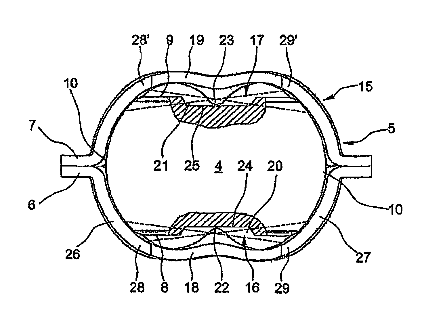
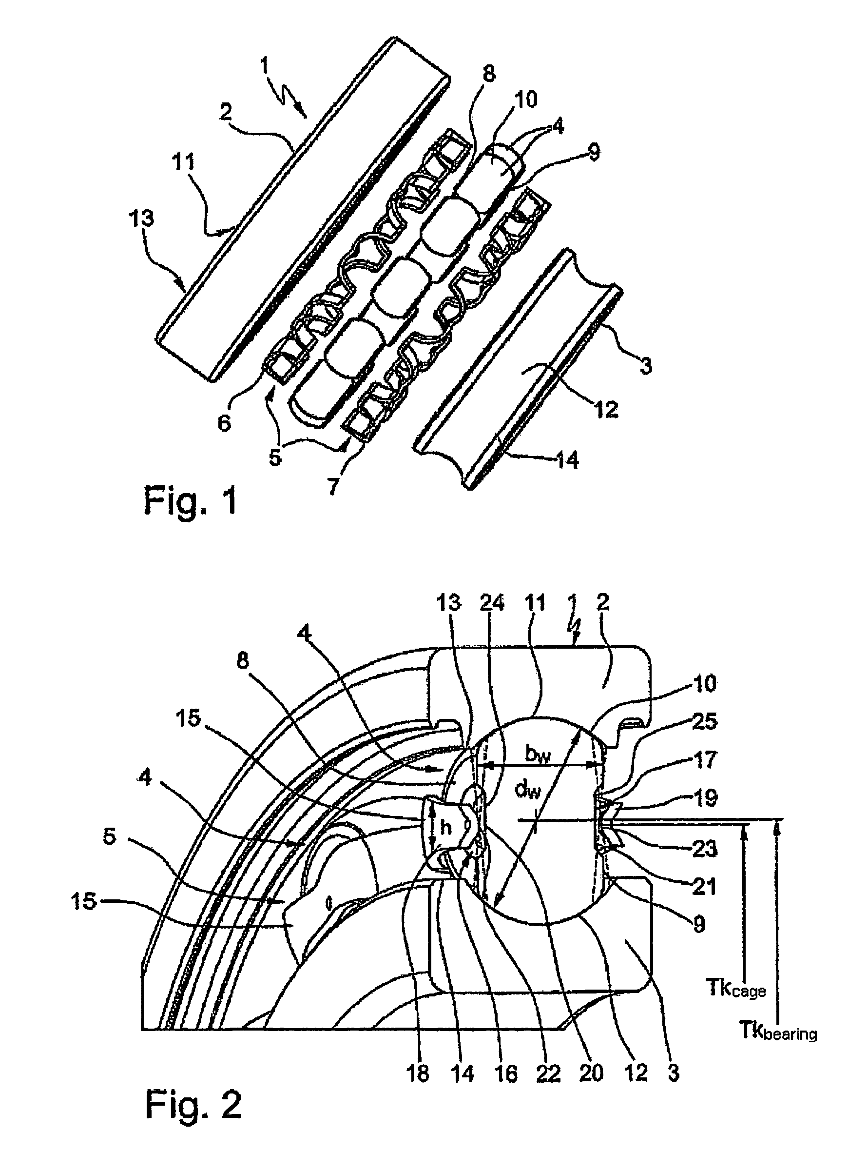
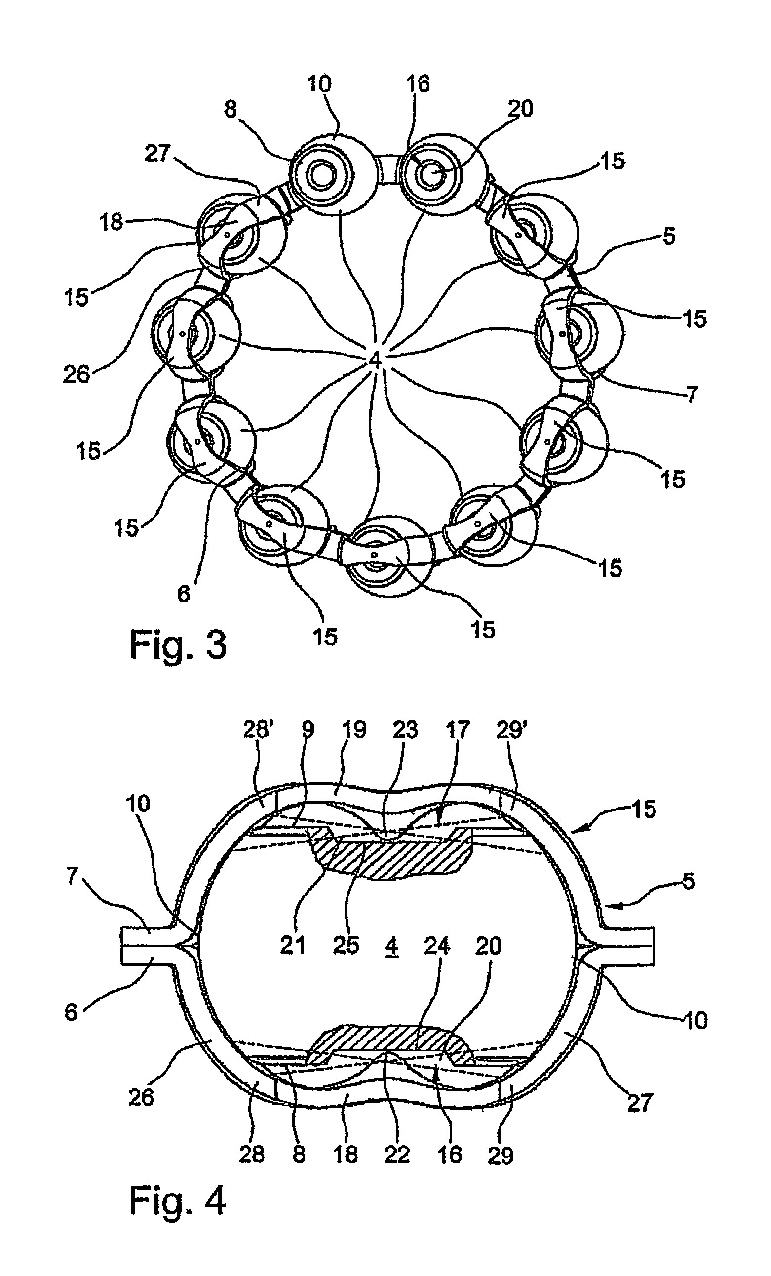
[0022]It may be gathered clearly from the exploded illustration according to FIG. 1 that a radial rolling bearing 1 designed as a single-row grooved rolling bearing consists essentially, in a similar way to known grooved ball bearings, of an outer bearing ring 2 and of an inner bearing ring 3 and also of a multiplicity of rolling bodies 4 arranged between these bearing rings 2, 3. The rolling bodies 4 are in this case formed, as can be seen clearly, by what are known as spherical disks which each have two side faces 8, 9 flattened symmetrically from a basic spherical shape and arranged parallel to one another and roll with their running surfaces 10 in two groove-shaped raceways 11, 12 which are in each case incorporated into the inside 13 of the outer bearing ring 2 and into the outside 14 of the i...


PUM


Abstract

A radial antifriction bearing which has an outer bearing ring, an inner bearing ring and a multitude of rollers, arranged between the bearing rings and held by a bearing cage. The rollers are configured as spherical disks that each have two parallel lateral surfaces which are symmetrically flattened from a basic spherical shape. The bearing cage has cage pockets in which the rollers are axially guided between the bearing rings via two low-friction point contacts between the center areas of their lateral surfaces and the longitudinal webs of the cage pockets. The rollers have a defined degree of freedom for tilt movements exerted at an angle to the running direction and a defined degree of freedom for self-adjustment to the pressure angle of the radial antifriction bearing.

Description

FIELD OF THE INVENTION[0001]The invention relates to a radial rolling bearing which can be implemented particularly advantageously on single-row grooved rolling bearings in motor vehicle transmissions, within the secondary drive of internal combustion engines or in electric brakes.BACKGROUND OF THE INVENTION[0002]It is generally known to a person skilled in the art of rolling bearings that single-row grooved ball bearings are rigid radial rolling bearings which cannot be dismantled and which are distinguished, above all, in that their radial and axial carrying capacity are equally high, and in that, because of their low friction, they have the highest rotational speed limits of all types of bearings. These grooved ball bearings have been known for a long time and consist essentially of an outer bearing ring and of an inner bearing ring and also of a number of balls which are arranged as rolling bodies between the bearing rings and which are guided at uniform distances from one anoth...

Claims


Application Information

Patent Timeline
Patent Type & Authority Patents(United States)
IPC IPC(8): F16C33/46
CPCF16C19/26F16C33/36F16C33/565F16C33/4682F16C33/547F16C33/4635F16C33/541F16C2361/45Y02T10/86F16C19/04F16C33/38F16C33/52
Inventor HOFMANN, HEINRICHDOPPLING, HORSTBOHR, ANDREASEIDLOTH, RAINER
Owner SCHAEFFLER TECH AG & CO KG
Why Eureka
Try Eureka