
Grain unloading conveyor with directable spout and closure apparatus and system

a conveyor and unloading technology, applied in the direction of loading/unloading vehicle arrangment, transportation items, refuse collection, etc., can solve the problems of only providing minimal grain flow control and guidance, boots do not provide closure capability to prevent entry, and boots are not typically adjustable, so as to limit or prevent contamination entry and increase grain distribution flexibility

Active Publication Date: 2011-05-10
BLUE LEAF I P INC
View PDF29 Cites 25 Cited by
  • Summary
  • Abstract
  • Description
  • Claims
  • Application Information

AI Technical Summary

Benefits of technology

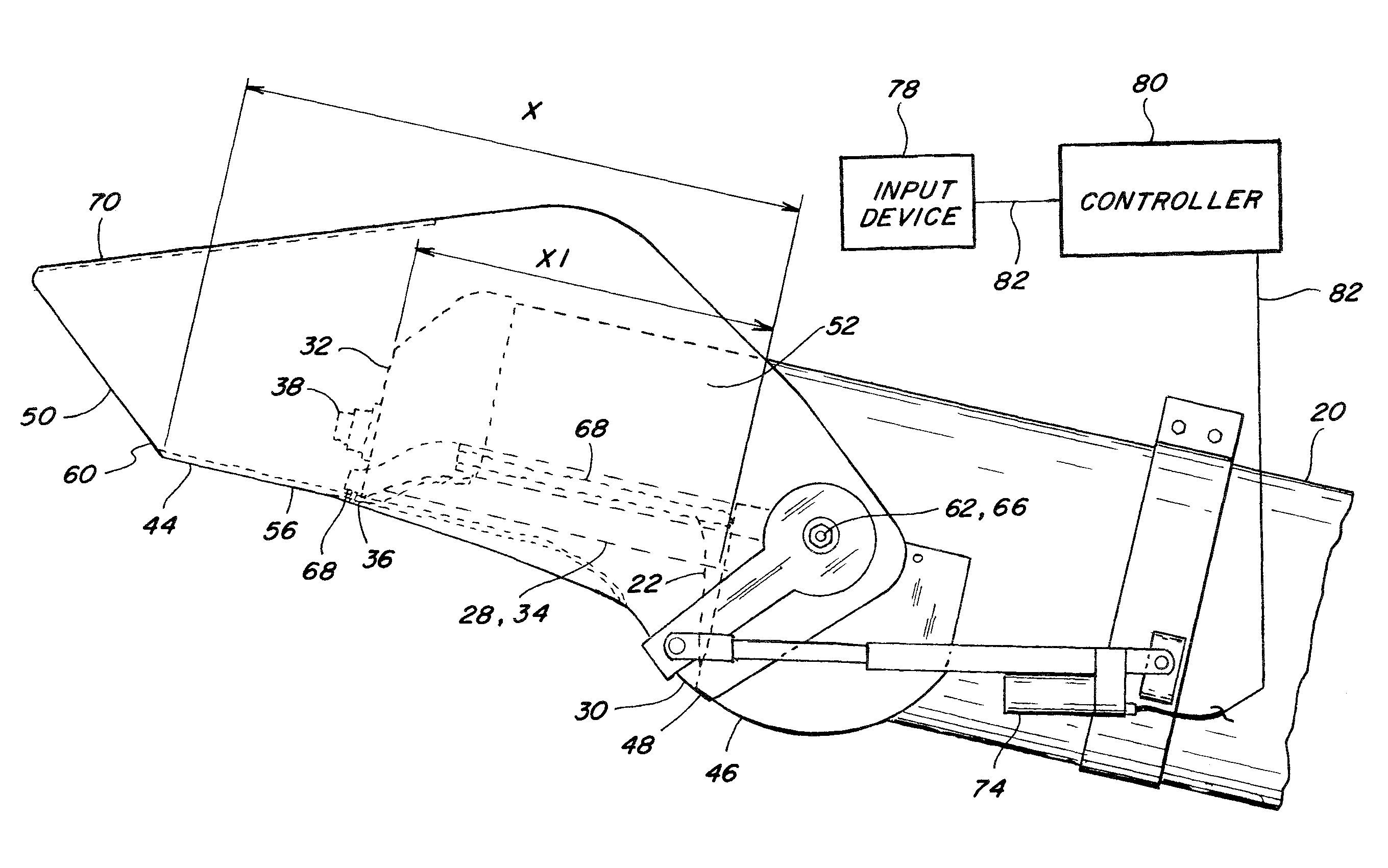
[0012]According to another preferred aspect, the spout assembly and system of the invention includes an elongate spout having a first open end portion, an opposite second open end portion, and spaced apart upwardly extending sidewall portions and a bottom therebetween, defining an upwardly open channel extending between the open end portions. The first open end portion of the spout includes a lower portion having a transverse shape at least substantially conforming to and marginally larger than the protuberance and is disposed therearound. The first open end portion has elements disposed above the lower portion, and includes pivot joints connecting to the tube and configured for allowing pivotal movement of the spout relative to the tube through a range of positions between a fully open position extending downwardly from the tube, and a closed position extending generally parallel to the tube in covering relation to the discharge opening. The lower portion of the first open end portion and the protuberance cooperate to prevent passage of grain therebetween and thus dribbling both when the spout is open and closed, and the sidewall portions preferably extend upwardly at least to side portions of the peripheral edge portion of the tube when the spout is in the partial and fully open positions to prevent grain loss therebetween, and to also reduce disturbance of grain flow by side winds.
[0013]According to another preferred aspect, the spout assembly and system of the invention includes an actuator connected to the spout and controllably operable for moving the spout through the range of positions between the fully open position and the closed position to enable adjusting the location of the flow of grain from the conveyor, for example, to compensate for any of the changing conditions discussed above. To facilitate adjustability, the spout preferably has a longitudinal extent greater than the longitudinal extent of the discharge opening, which beneficially increases the distance that the outflowing grain can travel longitudinally from the tube, and thus the effective length of the conveyor, and also allows providing a greater span of adjustability of grain delivery. It also allows the second or free end of the spout when closed to extend beyond the end of the tube, which also allows it to be covered, to provide greater grain delivery accuracy and control, particularly when windy.
[0016]According to additional preferred aspects of the invention, the spout can be configured such that when in the closed position, it forms a sealed condition in cooperation with adjacent regions of the tube, to limit or prevent entry of contaminants, e.g., moisture, dust, straw, leaves, birds, rodents, and the like. The spout can also include a cover portion over the open channel adjacent to the second end portion, for further guiding and containing the grain flow. The cover portion can be positioned and configured so as to be located endwardly beyond the discharge end of the tube when the spout is in the closed position, and can include structure so as to release or break open in the event a force is exerted thereagainst from within the channel, such as by deadheaded grain or the like. In this latter regard, the spout can optionally be constructed of a rigid, yet yieldable plastics material, so as to also resist damage from impacts and the like, and so as to be sufficiently deformable to pass over the upper portion of a side or end of a grain receiver in the event of contact therewith. Further, the discharge end of the tube and the spout can be rotatable laterally about the tube, to enable increased flexibility of grain distribution, and for storage in the closed position.

Problems solved by technology

However, such boots are not typically adjustable, and provide only minimal grain flow control and guidance, and little or no extension of the effective length of the conveyor.
Such boots also do not provide a closure capability to prevent entry of contaminants, nor an ability to prevent dribbling of grain after use.
This spout provides an extension ability, and some degree of remotely adjustable grain flow for an endwardly facing discharge opening, but provides no closure capability whatsoever, nor does it prevent grain dribbling.
However, no closure nor dribble prevention is provided, and the directional control capability is limited essentially to the region directly below the funnel, and no substantial effective length extension is achievable.
This can be relatively easy to accomplish if the harvester and receiving truck or wagon are stationary, but becomes more difficult if the harvester and the receiving truck or wagon are moving, and the difficulty increases further if the terrain is uneven and / or sloped, and / or a strong, gusting, and / or direction changing wind is present.
Further, the grain holding capacity of many harvesters and receivers is quite large, and it may be required to have a capability to vary the grain flow location to spread the grain within a receiving truck or wagon to prevent spillage over the side of the receiver.

Method used


Image

  • Grain unloading conveyor with directable spout and closure apparatus and system
  • Grain unloading conveyor with directable spout and closure apparatus and system
  • Grain unloading conveyor with directable spout and closure apparatus and system

Examples


Embodiment Construction

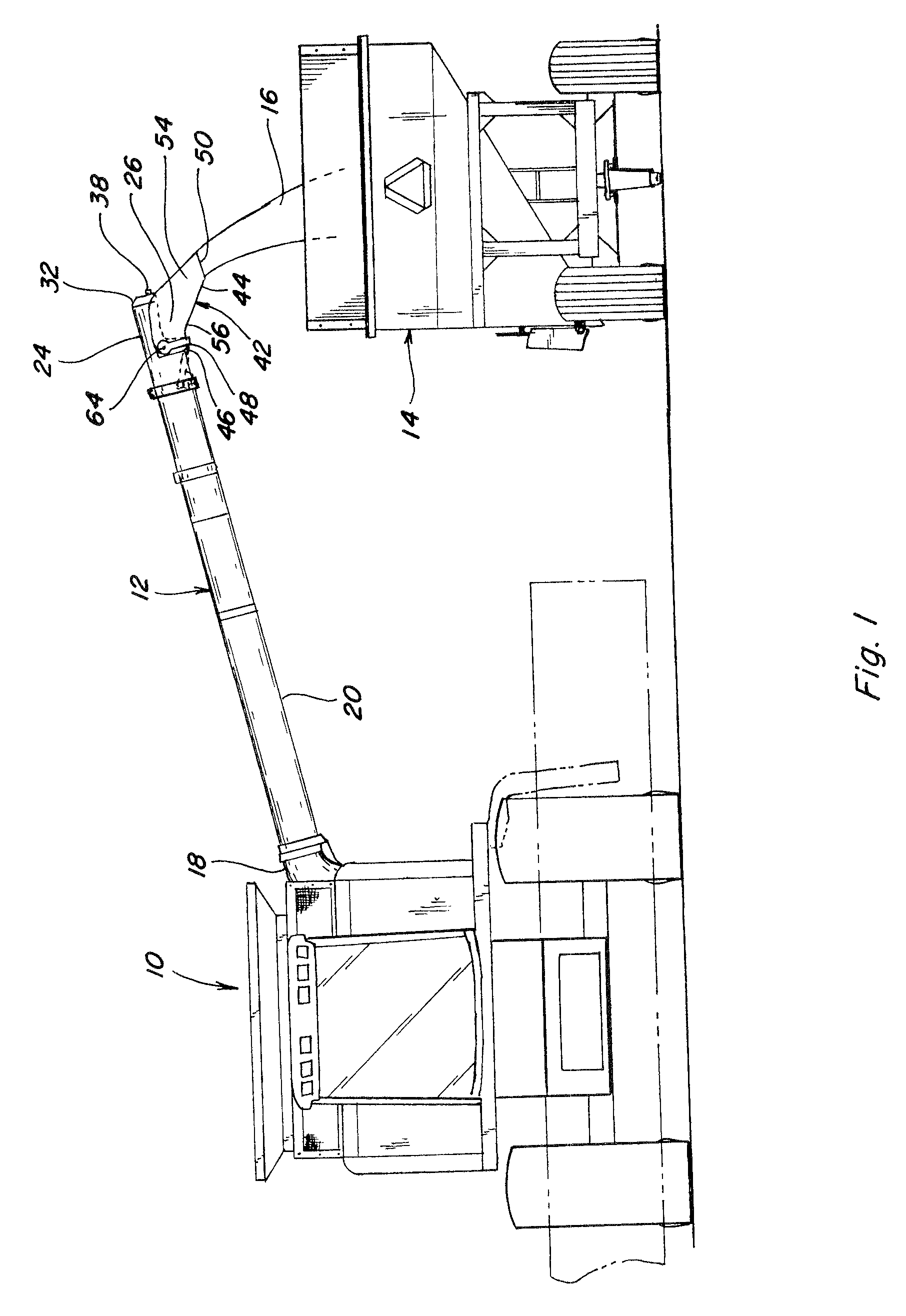
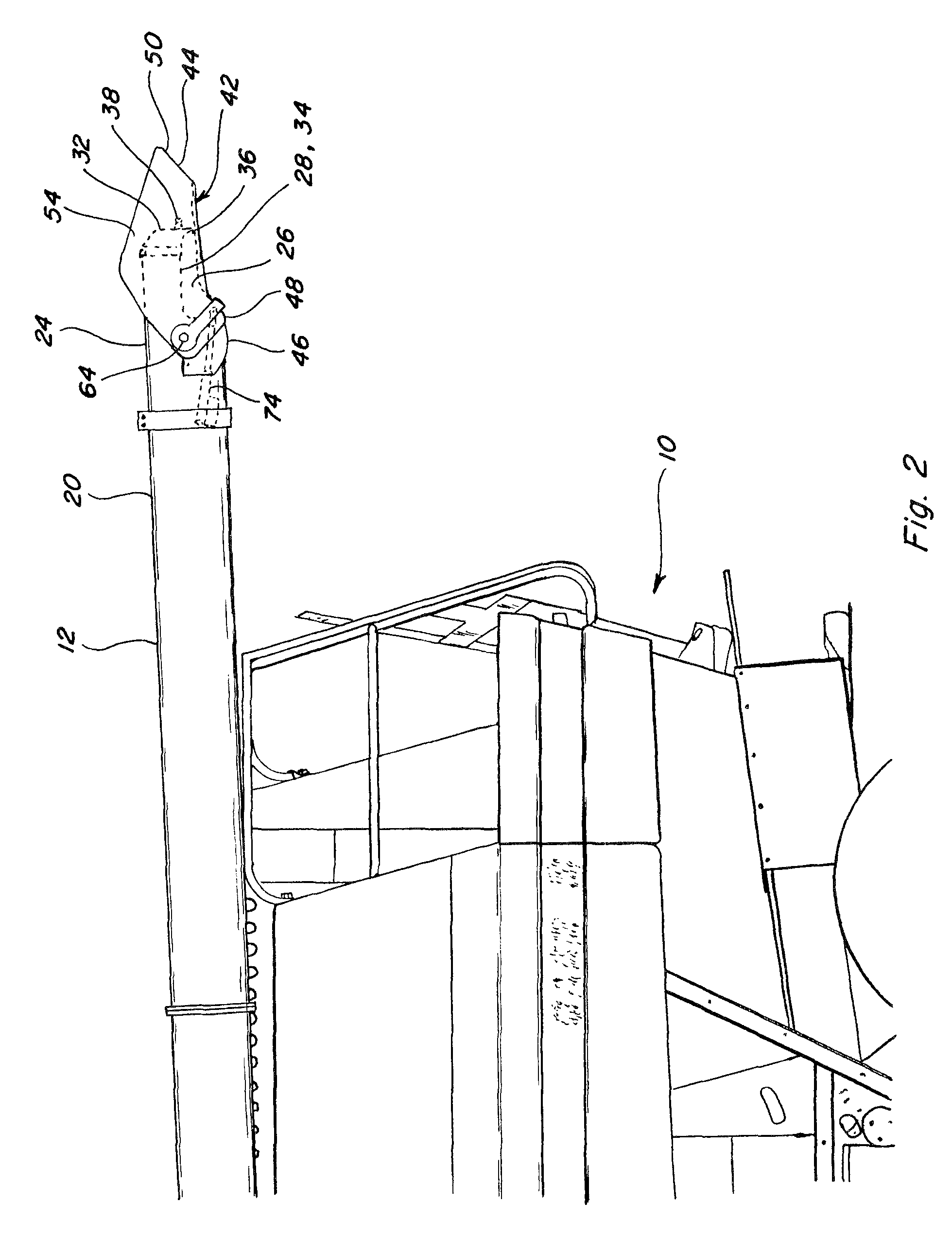
[0028]Referring now to FIGS. 1 and 2, a representative agricultural harvesting machine 10, which is a combine harvester of well-known construction and operation, is shown, including an unloading conveyor 12 constructed and operable according to the teachings of the present invention. In FIG. 1, unloading conveyor 12 is shown in a sidewardly and upwardly extending deployed or unloading position, for unloading grain into an accompanying container, which here is illustrated by a conventional agricultural grain wagon 14, in the well known manner. This is intended to be representative of a wide variety of unloading operations, wherein a flow of grain 16 from machine 10 is to be directed into a receiving container, such as wagon 14, periodically during operation of machine 10. In FIG. 2, unloading conveyor 12 is shown in a stored position extending rearwardly from a machine 10, also in the well known manner.

[0029]Unloading conveyor 12 generally includes a pivoting mounting end 18 connecti...


PUM


Abstract

An unloading conveyor apparatus and system for an agricultural harvester including a spout controllably directable for enabling distributing grain in a desired manner within a region of a receiving storage container, or a transporting truck, wagon, or other vehicle, and configurable as a closure for the conveyor for preventing entry of contaminants and the like. The spout can advantageously extend both the distance and range of variability of grain delivery location, and the free end of the spout can include a cover for improving grain delivery accuracy and wind resistance, and a break open feature to prevent damage. The spout can also be rotatable laterally about the end of the conveyor.

Description

TECHNICAL FIELD[0001]The present invention relates to an unloading conveyor apparatus and system for an agricultural harvester, and more particularly, to an unloading conveyor including a spout controllably directable for enabling distributing grain in a desired manner within a region of a receiving storage container, or a transporting truck, wagon, or other vehicle, and configurable as a closure for the conveyor for preventing entry of contaminants and the like.BACKGROUND ART[0002]Unloading of grain from harvesters such as combines, is typically accomplished using an elongate unloading conveyor. Such unloading conveyors typically are helical auger type conveyors contained in a tubular housing. The conveyors have a free or discharge end portion including a discharge opening through which the grain is propelled by the operation of the conveyor. On some conveyors, the discharge opening faces longitudinally or endwardly such that the grain is propelled more longitudinally outwardly, an...

Claims


Application Information

Patent Timeline
Patent Type & Authority Patents(United States)
IPC IPC(8): B60P1/40
CPCA01D41/1217
Inventor YODER, DENVER R.HORST, ANDREW J.
Owner BLUE LEAF I P INC
Learn More