
Correlation interval synchronization apparatus and method

a synchronization apparatus and interval technology, applied in the field of correlation interval synchronization apparatus and method for an orthogonal frequency division multiplexing (ofdm) system, can solve the problems of time-consuming operation of the conventional system and the inability to efficiently synchronize the fram

Active Publication Date: 2011-05-10
VIA TECH INC
View PDF3 Cites 7 Cited by
  • Summary
  • Abstract
  • Description
  • Claims
  • Application Information

AI Technical Summary

Benefits of technology

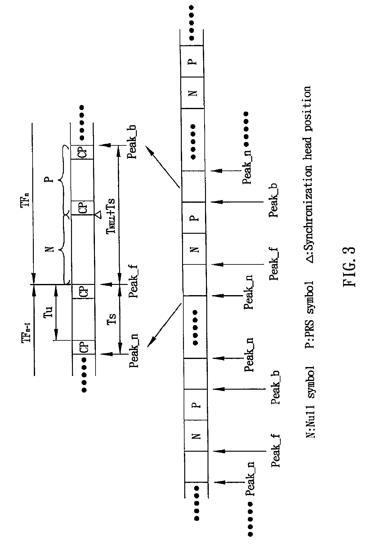
The present invention provides a correlation interval synchronization apparatus and method for acquiring synchronization head position of the transmission frame, and facilitating the frame synchronization at the receiver end. The invention also provides a window shift method that reduces time consumed in the operation and makes real-time operation suitable for the ASIC. Additionally, the invention provides an accuracy enhanced method for improving the synchronization accuracy. The correlation interval synchronization apparatus includes a correlation device, a peak search device, a peak interval determination device, and a synchronization head position identification device. The correlation device firstly performs correlation operation on received data, followed by searching for a number of peaks by the peak search device in accordance with the correlation value out of the correlation device. The peak interval determination device acquires a number of peak intervals in accordance with the peaks, and determines a peak interval where a synchronization head position resides in accordance with the length of the peak intervals. The synchronization head position identification device finally identifies the synchronization head position in accordance with the peak interval where the synchronization head position resides.

Problems solved by technology

The conventional system requires time-consuming operations.
Take the algorithm (1) for example, as substantial time is consumed in the division operations, efficient frame synchronization becomes impossible.

Method used


Image

  • Correlation interval synchronization apparatus and method
  • Correlation interval synchronization apparatus and method
  • Correlation interval synchronization apparatus and method

Examples


Embodiment Construction

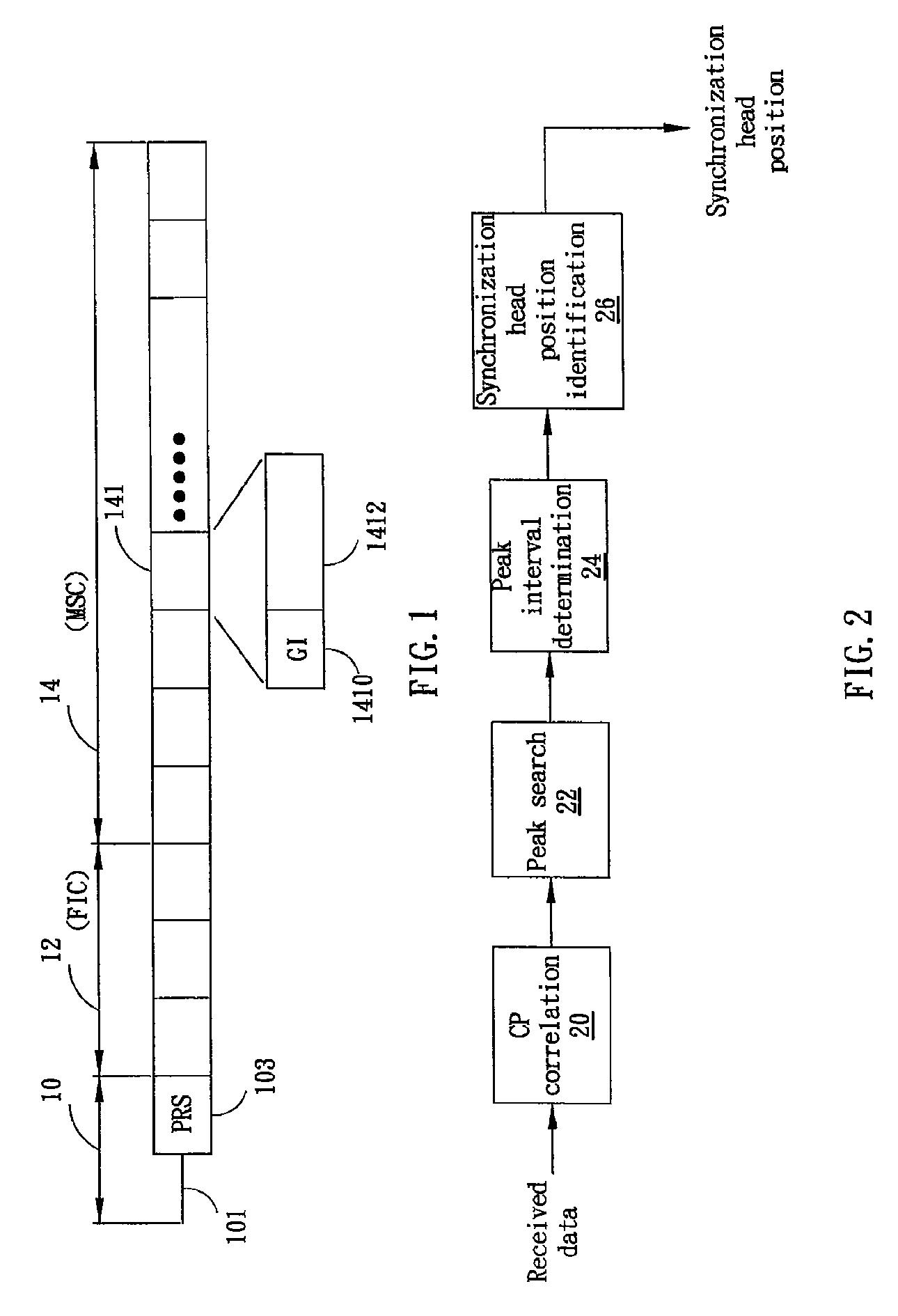
[0017]FIG. 1 schematically shows a transmission frame of a Terrestrial Digital Multimedia Broadcasting (TDMB) system or a Digital Audio Broadcasting (DAB) system, which applies orthogonal frequency division multiplexing (OFDM) technique according to one embodiment of the present invention. The DAB / TDMB transmission frame includes a synchronization channel 10, a fast information channel (FTC) 12, and a main service channel (MSC) 14. Specifically, the synchronization channel 10 includes a null symbol 101 and a phase reference symbol (PRS) 103. The null symbol 101 has emitted with energy less than other symbols of the transmission frame or even with no energy, and may be used for synchronization purpose in the embodiment. The phase reference symbol 103 is used as a reference for demodulation of, for example, differential quadrature phase shift keying (DQPSK). The fast information channel 12 includes control information, which defines the sequence and the length (or size) of symbols in ...


PUM


Abstract

The present invention is directed to a correlation interval synchronization apparatus and method. Correlation is firstly performed on received data, followed by searching peaks in accordance with the output of the correlation. Subsequently, peak intervals are acquired according to the peaks, and the peak interval where the synchronization head position resides is determined. Finally, the synchronization head position is identified within the associated peak interval.

Description

BACKGROUND OF THE INVENTION[0001]1. Field of the Invention[0002]The present invention generally relates to synchronization apparatus and method, and more particularly to correlation interval synchronization apparatus and method for an orthogonal frequency division multiplexing (OFDM) system.[0003]2. Description of the Prior Art[0004]Orthogonal frequency division multiplexing (OFDM) is a communication technique that applies frequency division and multi-carrier modulation, and is widely employed in a variety of digital communication systems, such as the Digital Multimedia Broadcasting (DMB) system or the Digital Audio Broadcasting (DAB) system. The DMB is a digital wireless communication system established on the DAB standard for transmitting multimedia data to a portable device, such as a cellular telephone. In the DMB system, the controllability of time offset of a frame is a critical factor for the efficiency of a receiver. In the conventional system, such as the system disclosed i...

Claims


Application Information

Patent Timeline
Patent Type & Authority Patents(United States)
IPC IPC(8): H03D1/00H04L27/06
CPCH04B1/7075H04L27/2678H04L27/2656H04L7/08
Inventor YUAN, XUELEI, MIN
Owner VIA TECH INC
Learn More