Method and system for adjusting 3D CT vessel segmentation

a technology of adjusting system and 3d ct, applied in image analysis, image enhancement, instruments, etc., can solve the problems of symptomatic patients already at an advanced stage, soft plaque is not easily detectable, and the procedure is only performed on symptomatic patients

Active Publication Date: 2011-05-10
GENERAL ELECTRIC CO
View PDF11 Cites 75 Cited by
  • Summary
  • Abstract
  • Description
  • Claims
  • Application Information

AI Technical Summary

Benefits of technology

[0008]In another embodiment, a method for defining an object within a diagnostic image comprises segmenting an elongated object within a diagnostic image to detect a contour of the elongated object which has radial and longitudinal directions. Cross-sectional planes are defined within the object in the radial direction. Each of the cross-sectional planes has radial lines extending beyond the contour of the object. An optimal intersection point is selected along each of the radial lines to define an intersection of the cross-sectional plane with the contour. The optimal intersection points are based on at least one of minimizing discontinuities between the radial lines located on adjacent cross-sectional planes and minimizing discontinuities between adjacent radial lines located on the same cross-sectional plane. The elongated object is fitted with a 3D mesh having cross-sectional splines and longitudinal splines formed along the contour in the radial and longitudinal directions, respectively. The splines are based on at least the optimal intersection points.

Problems solved by technology

Typically in x-ray or non-contrasted CT studies, soft plaque is not easily detectable.
However, the procedure is only performed on symptomatic patients due to its invasive nature.
Unfortunately, symptomatic patients are already at an advanced stage and past non-invasive therapy options.
However, automated methods do not exist and thus standardization and productivity suffer due to the volume of data to be reviewed and manually processed.

Method used


Image

  • Method and system for adjusting 3D CT vessel segmentation
  • Method and system for adjusting 3D CT vessel segmentation
  • Method and system for adjusting 3D CT vessel segmentation

Examples


Embodiment Construction

s or memories) may be implemented in a single piece of hardware (e.g., a general purpose signal processor, random access memory, hard disk, or the like). Similarly, the programs may be stand alone programs, may be incorporated as subroutines in an operating system, may be functions in an installed software package, and the like. It should be understood that the various embodiments are not limited to the arrangements and instrumentality shown in the drawings.

DETAILED DESCRIPTION OF THE INVENTION

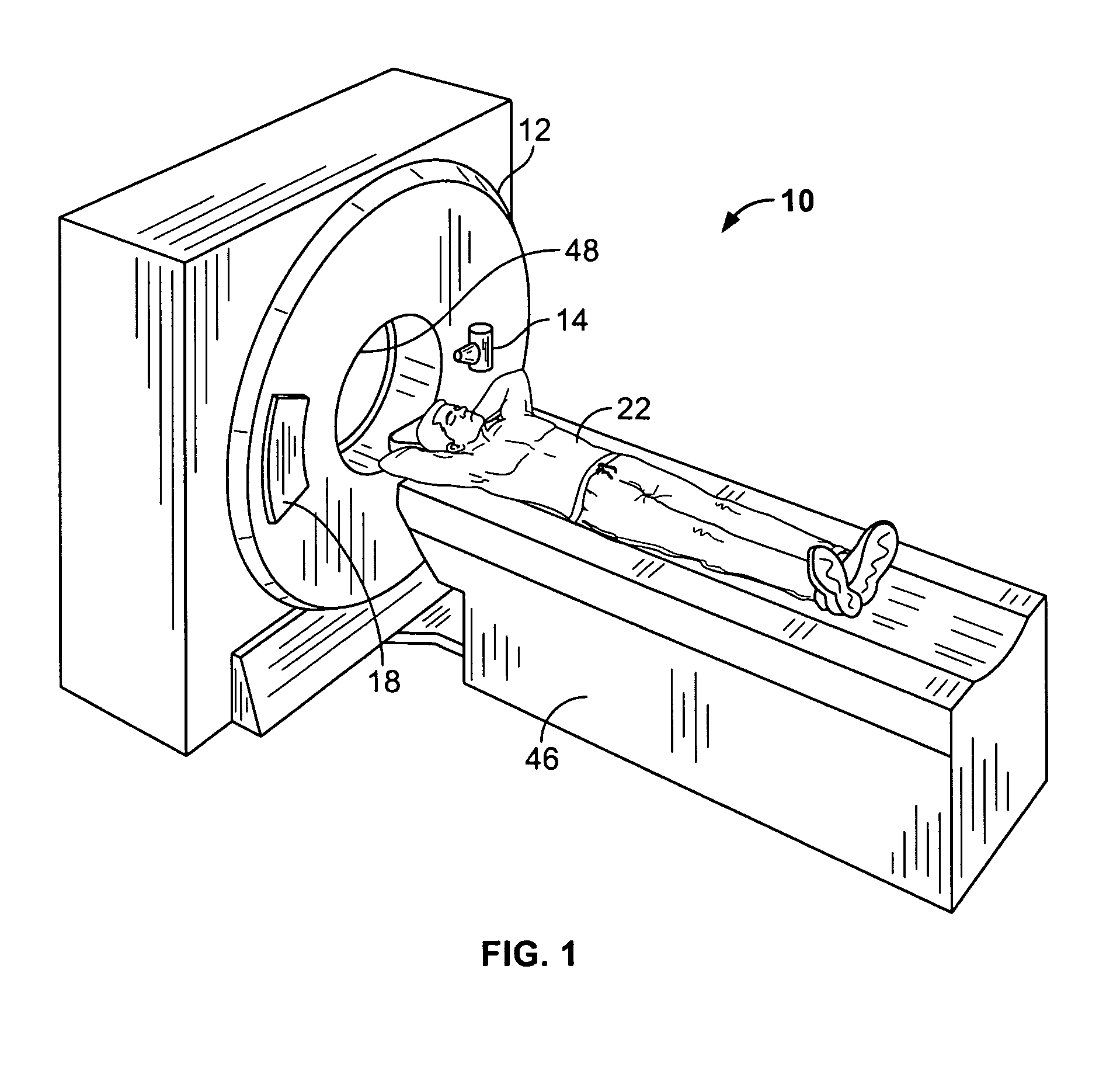
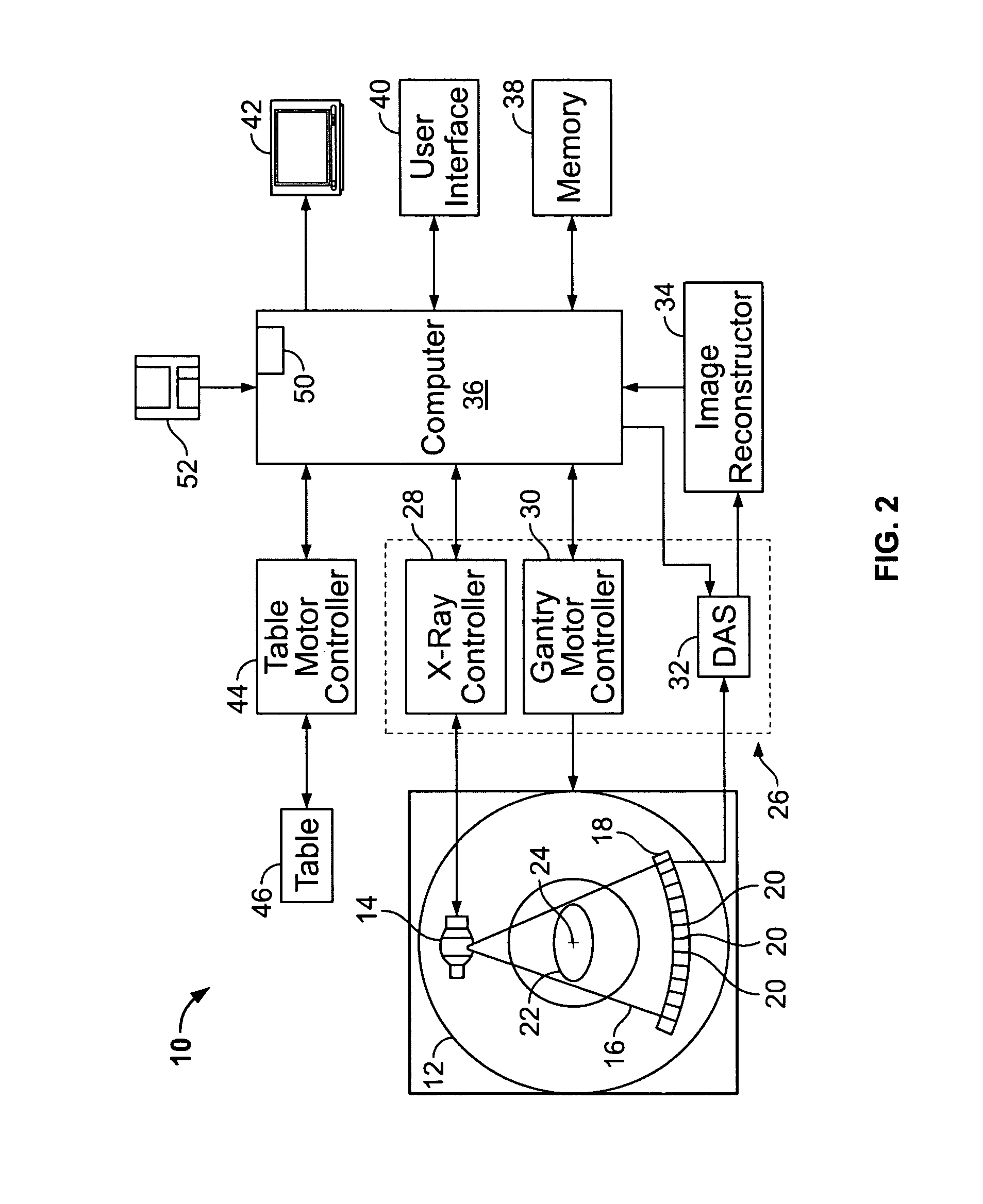
[0021]FIG. 1 illustrates a pictorial view of a computed tomography (CT) imaging system 10. The system 10 includes a gantry 12 representative of a “third generation” CT imaging system. FIG. 2 illustrates a block diagram of the system 10 of FIG. 1, and will be discussed together with FIG. 1.

[0022]The gantry 12 has an x-ray source 14 that projects a beam of x-rays 16 toward a detector array 18 on the opposite side of the gantry 12. The detector array 18 is formed by a plurality of detector rows (...


PUM


Abstract

Method and system for processing an object within a diagnostic image comprises segmenting a three dimensional (3D) object within a diagnostic image. A contour of the object is fitted with a 3D mesh comprising splines in at least first and second directions. The splines provide a plurality of editable control points, and the splines in the first direction intersect with the splines in the second direction at intersection points. A position of at least one control point on the 3D mesh is adjusted based on a user input.

Description

BACKGROUND OF THE INVENTION[0001]This invention relates generally to processing computer tomography (CT) datasets, and more particularly, to detecting contours of elongated structures such as blood vessels within CT datasets.[0002]Cardiovascular related deaths constitute more than 500,000 people annually in the USA, and much more globally. A major portion of the deaths are attributed to coronary artery disease, where the chief culprit is the build up of plaque, such as soft plaque and its ruptures, as well as hard plaque or calcification.[0003]Typically in x-ray or non-contrasted CT studies, soft plaque is not easily detectable. Calcified plaque, therefore, has been used as a surrogate for the presence of soft plaque, based on the reasoning that calcified plaque is the by-product of ruptured plaque. Coronary plaque has been classified into six stages according to the Stary scale. According to general consensus, it is crucial to determine the plaque in stages 4 and 5 as the plaque co...

Claims


Application Information

Patent Timeline
Patent Type & Authority Patents(United States)
IPC IPC(8): G06K9/00G06V10/26
CPCG06K9/34G06T7/0083G06T2207/30101G06T2207/20096G06T2207/10081G06T7/12G06V10/26
Inventor SKINNER, JOHN V.AVINASH, GOPAL B.LE NEZET, PATRICIADUTTA, SANDEEPSIROHEY, SAAD AHMEDHAAS, DEANN MARIE
Owner GENERAL ELECTRIC CO
Why Eureka
Try Eureka