Heat sink

a technology of heat sink and heat pipe, which is applied in the direction of lighting and heating apparatus, semiconductor devices, basic electric elements, etc., can solve the problems of large quantity of heat pipes needed for those prior art devices, increased manufacturing costs dimensional expansion of prior art devices, so as to achieve the effect of reducing the thermal resistance of the base plate and improving the heat radiating characteristics

Inactive Publication Date: 2011-05-17
FUJIKURA LTD
View PDF37 Cites 8 Cited by
  • Summary
  • Abstract
  • Description
  • Claims
  • Application Information

AI Technical Summary

Benefits of technology

[0010]It is an object of the present invention to provide a heat sink capable of cooling an electron device efficiently, by radiating heat of the electron device efficiently into the air. More specifically, an object of the present invention is to provide a heat sink, which has an enlarged substantial heat radiation area, and which allows the air to flow between heat radiation fins in various directions. Another object of the invention is to reduce thermal resistance between the electron device and the heat radiation fins.
[0011]According to the heat sink of the present invention, the heat radiation fins are structured to enhance its heat transporting capability, and the heat pipe is employed as an auxiliary heat transfer means to support mainly a heat radiating portion of the fins. For this purpose, the heat radiating fins are extended laterally from a base plate to which an electron device is attached so as to promote a vertical moving of the air flowing therebetween. In case of natural cooling, for example, ascent of the airflow whose temperature is raised as a result of a heat radiation is promoted. Moreover, in case of carrying out a compulsory cooling using a fan, the air is promoted to flow downwardly and the base plate to which the electron device is contacted is thereby cooled. In order to dissipate the heat more efficiently, the heat pipe is arranged to connect the extended portion of the heat radiation fins and the base plate.
[0017]Further, the base plate as the vapor chamber can be thinned by fitting a reinforcement frame therewith. The thermal resistance of the base plate is thereby further lowered, and the heat radiating characteristics is consequently improved.

Problems solved by technology

This means that a large quantity of heat pipes are necessary for those prior art devices.
For this reason, such prior art devices have to be dimensionally enlarged and a manufacturing cost thereof also be increased.
This means that thermal resistance between the electron device and the heat radiation fins is large, and this degrades the cooling performance to cool the electron device.
For this reason, heat radiating efficiency of the heat sink of this kind is not sufficiently high enough.

Method used


Image

  • Heat sink
  • Heat sink
  • Heat sink

Examples


Embodiment Construction

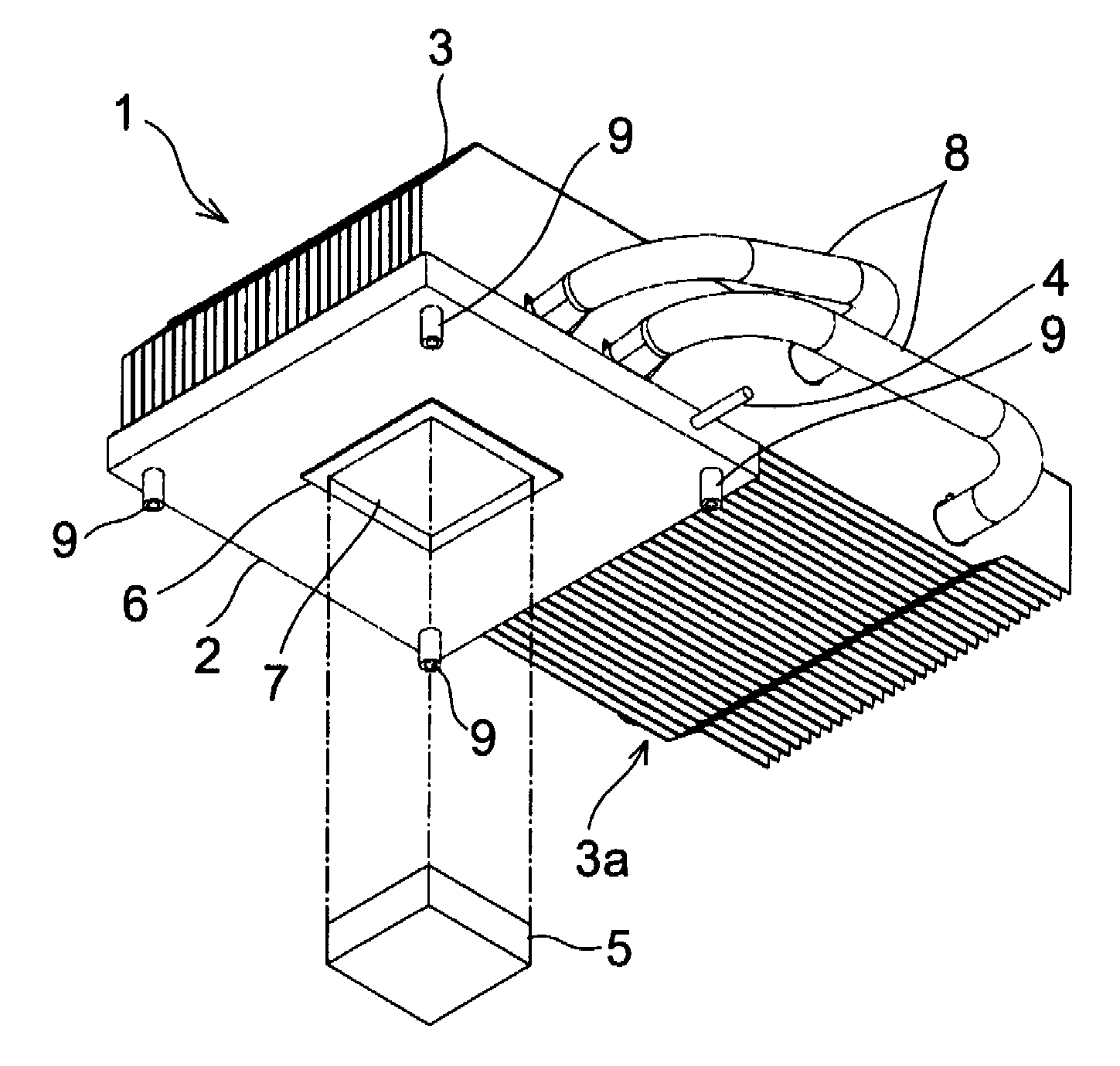
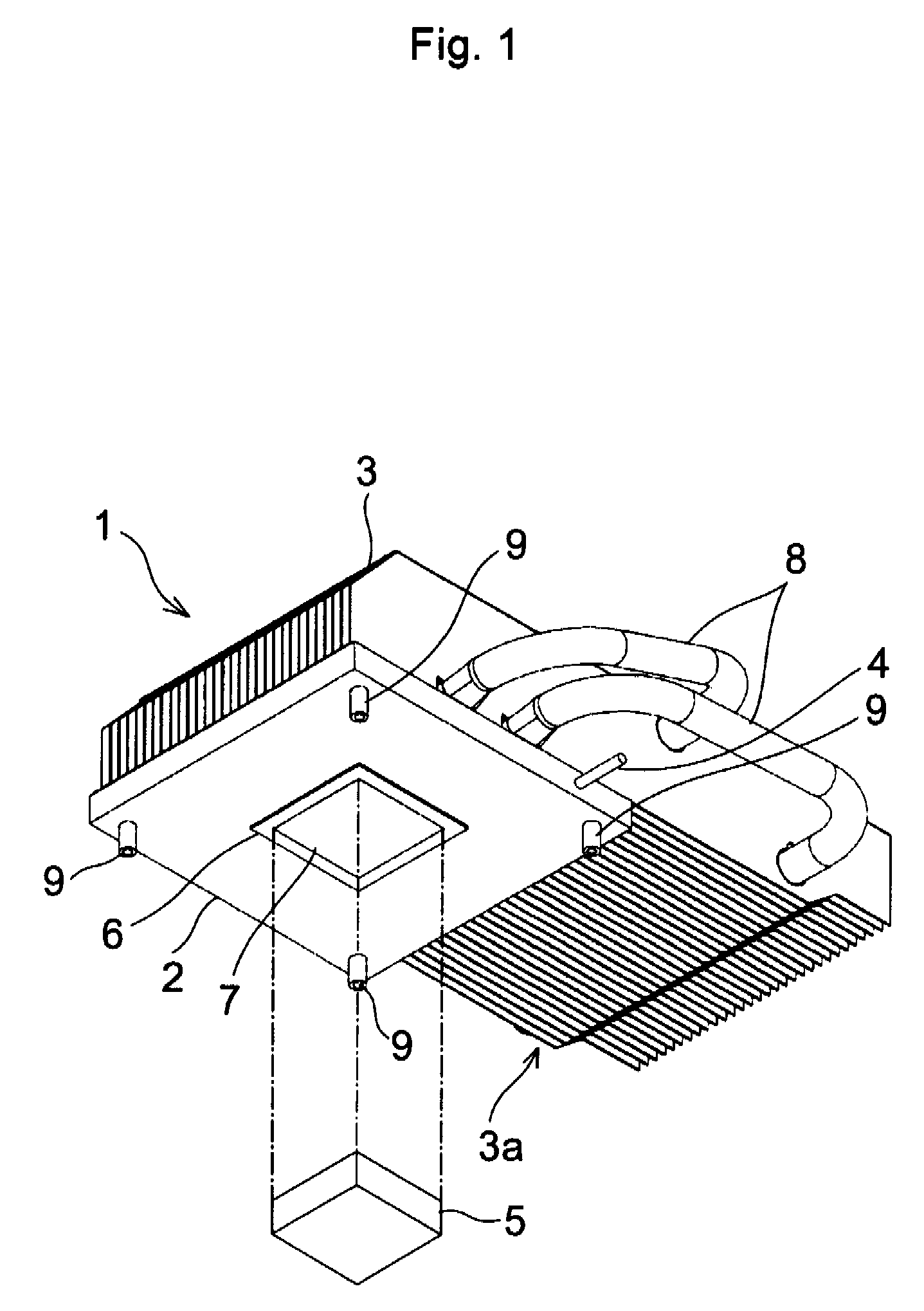
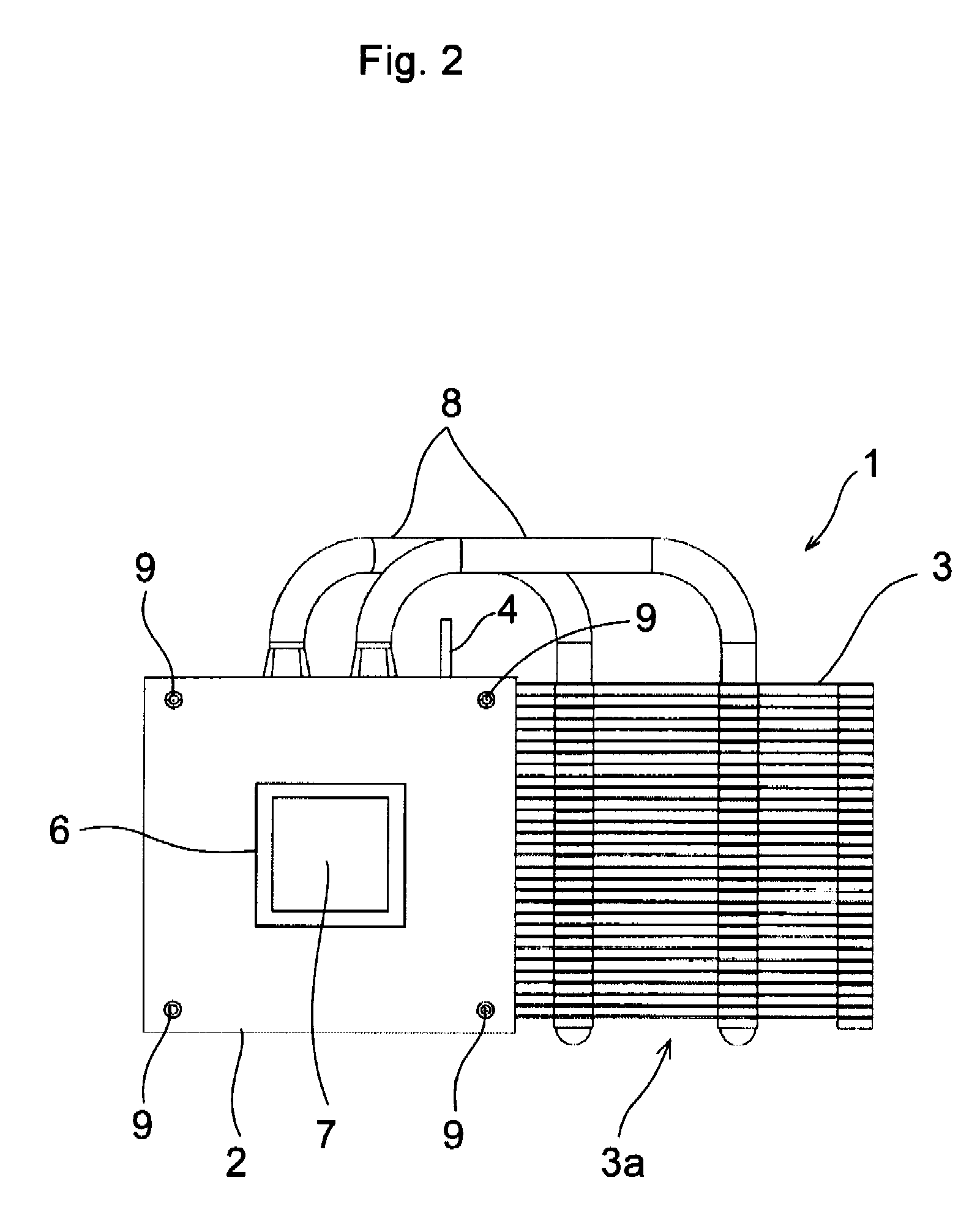
[0025]One example of the present invention is illustrated in FIGS. 1 to 3. The illustrated heat sink 1 comprises a base plate 2 and a plurality of heat radiation fins 3 erected integrally on an upper face of the base plate 2. A shape of the base plate 2 may be determined arbitrarily. For example, the base plate 2 may be formed into a geometrically refined shape such as a square shape, a rectangular shape or a circular shape. Otherwise, the base plate 2 may also be shaped into an irregular shape such as a star shape. The base plate 2 may be a flat heat pipe or a flat vapor chamber. The flat heat pipe or vapor chamber is a device for transporting heat comprising an evacuated hollow container, and a condensable working fluid such as water encapsulated in the container. In the heat pipe or vapor chamber, the heat is transported in the form of latent heat of the working fluid. In FIGS. 1 to 3, a reference numeral 4 represents a nozzle. The air is evacuated from the nozzle 4 and the vapor...


PUM


Abstract

A heat sink, wherein a plurality of heat radiation fins are mounted on a base plate to which an electronic device is attached in a heat transmittable manner. The heat radiation fins are erected vertically and in parallel with each other on the reverse face of the base plate to which the electron device is contacted, and extended laterally from the base plate. A heat pipe transports heat between the extended portion of the heat radiation fins and the base plate.

Description

CROSS-REFERENCE TO RELATED APPLICATION[0001]This application claims benefit of U.S. Provisional Application No. 60 / 911,020 filed Apr. 10, 2007; the entire disclosure thereof which is incorporated by reference.BACKGROUND OF THE INVENTION[0002]1. Field of the Invention[0003]The present invention deals with a heat sink for cooling an electron device or electronic device such as an IC (i.e., Integrated Circuit) or an IC chipset by radiating heat thereof into the air.[0004]2. Discussion of the Related Art[0005]U.S. Pat. Nos. 6,102,110 and 7,143,819 disclose devices for cooling an electron device by transporting heat generated by the electron device to a portion away from a contact portion of the electron device to radiate the heat therefrom. According to the structure taught by U.S. Pat. No. 6,102,110, one of the end portion of a plurality of heat exchange tubes are secured in a rigid plate, and the other end portion of the heat exchange tubes are protruded from the rigid plate. A plural...

Claims


Application Information

Patent Timeline
Patent Type & Authority Patents(United States)
IPC IPC(8): F28D15/02
CPCH01L23/427H01L2924/0002H01L2924/00
Inventor MOCHIZUKI, MASATAKA
Owner FUJIKURA LTD
Why Eureka
Try Eureka