
Air humidifier for respirators and incubators

a technology for air humidifiers and incubators, which is applied in the direction of lighting and heating apparatus, heating types, and separation processes, etc., can solve the problems of contaminated water reserves, less complicated design or handling, and the total amount of water must at first be heated up before the humidifier can deliver its full moistening capacity. , to achieve the effect of simple design

Inactive Publication Date: 2011-05-17
DRAGERWERK AG
View PDF20 Cites 21 Cited by
  • Summary
  • Abstract
  • Description
  • Claims
  • Application Information

AI Technical Summary

Benefits of technology

[0007]The object of the present invention is to provide an air humidifier for respirators and incubators, which is operated at the boiling point of water, and which has a simple design and offers the possibility of removing and cleaning the parts that come into contact with the breathing gas and the water, for example, in a dishwasher.
[0008]The object is accomplished inside a device for adding moisture to breathing gas of a patient. An evaporator defines an evaporator volume, and boils the liquid inside the evaporator volume. A mixing chamber is in communication with the evaporator volume and mixes the vapor or moisture from the liquid in the evaporator with the breathing gas of the patient. The mixing chamber is a separate structure from the evaporator. The mixing chamber and the evaporator are connected by a first connection that is repetitively connectable and disconnectable without significant destruction of a respective connection. The phrase “without significant destruction” is used to indicate that the connections are designed to operate for the expected lifetime of the evaporator, heater and breathing gas supply without repair or major modification. A heater is arranged outside of the evaporator and in a heat conducting connection with the evaporator. The heater is a separate structure than the evaporator. The evaporator and the heater are connected by a second connection that is repetitively connectable and disconnectable. A liquid storage tank is in communication with the evaporator and supplies a liquid to the evaporator through a flow channel. The liquid storage tank is larger than the evaporator. The flow channel is formed of a material and has a size to thermally insulate the evaporator from the liquid storage tank.
[0009]The essential advantage of the air humidifier according to the principal claim is that the electric heater is separated from the water storage tank and from the evaporator, both of which can be removed and cleaned separately. There are no electric contacts or components on the water storage tank and on the evaporator proper. The water storage tank is thermally separated from the evaporator, so that only a small amount of water is being heated and evaporated. The air humidifier can as a consequence also be heated up rapidly and it rapidly responds to changes in the set heating output.
[0010]The water tank and the evaporator can be manufactured at low cost, so that these components may also be offered as disposable articles. The air humidifier may also be operated with tap water, because the minerals deposited from the water can again be removed during cleaning, optionally by mechanical cleaning by brushing, especially because all relevant openings of the air humidifier are large enough.

Problems solved by technology

Various air humidifiers for respirators and / or incubators have been proposed, which are more or less complicated in terms of design or handling, or are associated with the risk that the water reserve used becomes contaminated with microbes due to their design.
This prior-art concept has, however, the drawback that the total amount of water must at first be heated up before the humidifier can deliver its full moistening capacity.
This may take up to 30 minutes, so that a patient connected to the moistener may not be sufficiently humidified during this time.
It is also disadvantageous in this arrangement that the water may become contaminated with microbes over time because the temperatures are not high enough.
The drawback of this arrangement is that not all the parts that come into contact with the water can be removed and cleaned in a simple manner.

Method used


Image

  • Air humidifier for respirators and incubators
  • Air humidifier for respirators and incubators
  • Air humidifier for respirators and incubators

Examples


Embodiment Construction

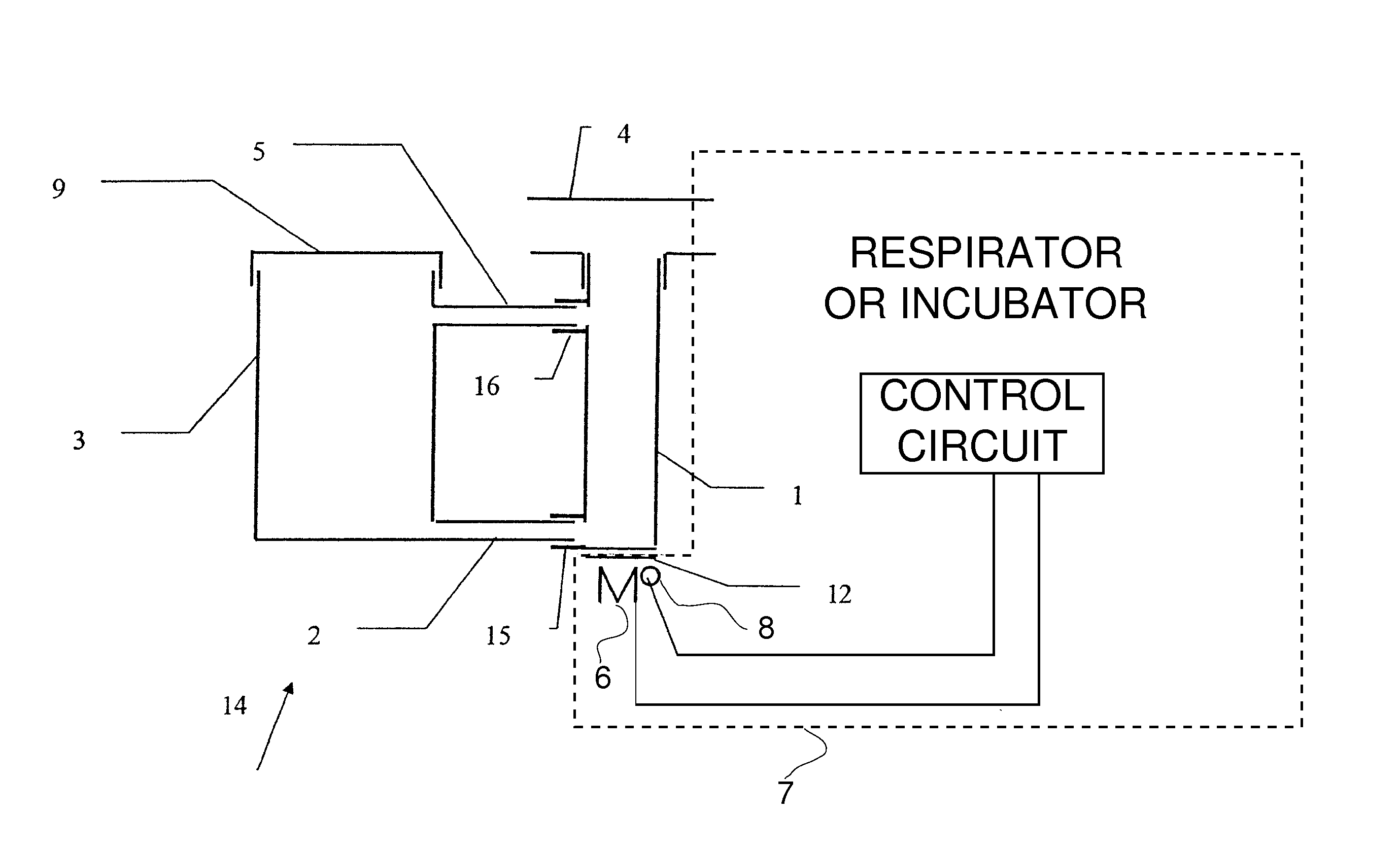
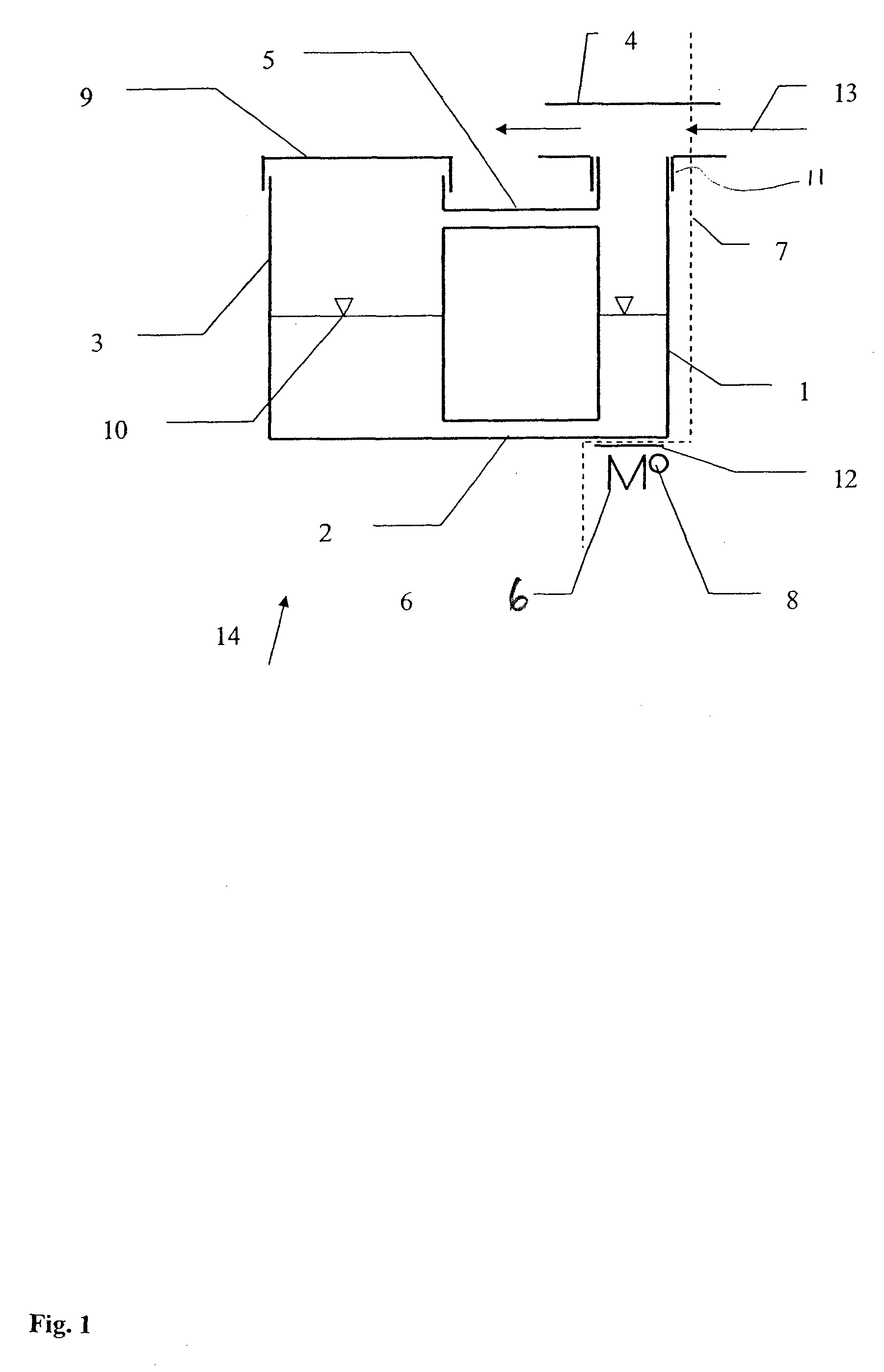
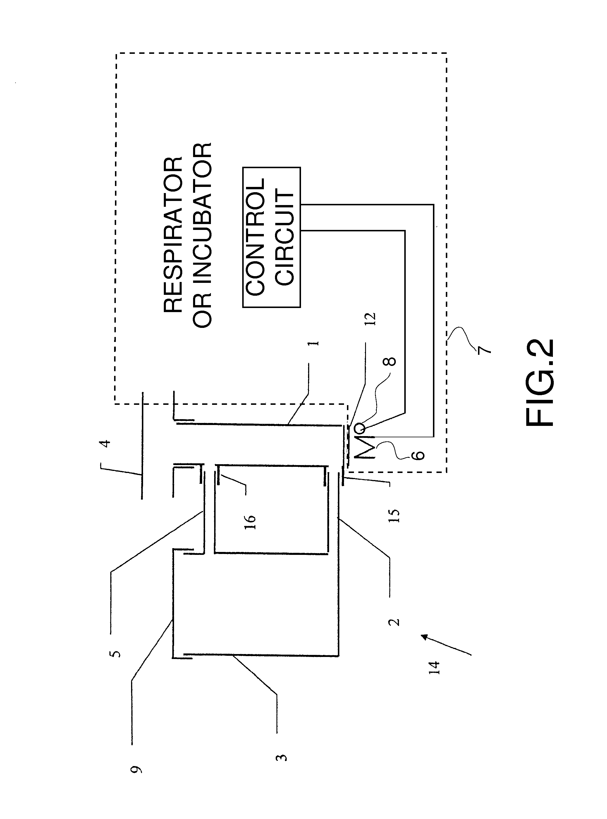
[0015]Referring to the drawings in particular, FIG. 1 shows an entire air humidifier 14 according to the invention. A liquid storage tank, preferably a water storage tank 3, is connected to an evaporator 1. The evaporator 1 is operated at the boiling point via a narrow flow channel 2 with a diameter of a few mm, which acts as a thermal insulation or sink The evaporator 1 is in thermal connection with the electric heater 6 of the device 7 (respirator or incubator) via the contact surface connection 12. The connection between the evaporator 1 and the heater 6 is preferably just a supporting connection where the weight of the evaporator 1 holds the evaporator 1 on the heater 6. The water level 10 is equal in the two tanks shown. The water storage tank 3 is closed airtightly against a respirator, not shown in more detail, with a cover 9. The heater 6 is controlled by a control circuit of the device 7 in terms of the temperature, measured by means of a temperature sensor 8, such as a PTC...


PUM

PropertyMeasurementUnit
lengthaaaaaaaaaa
internal diameteraaaaaaaaaa

Abstract

An evaporator defines an evaporator volume, and boils the liquid inside evaporator volume. A mixing chamber is in communication with the evaporator volume and mixes the vapor or moisture from the liquid in the evaporator with the breathing gas of the patient. The mixing chamber is a separate structure than the evaporator. The mixing chamber and the evaporator are connected by a first connection that is repetitively connectable and disconnectable without significant destruction of a respective connection. A heater is arranged outside of the evaporator and in a heat conducting connection with the evaporator. The heater is a separate structure than the evaporator. The evaporator and the heater are connected by a second connection that is repetitively connectable and disconnectable. A liquid storage tank is in communication with the evaporator and supplies a liquid to the evaporator through a flow channel. The liquid storage tank is larger than the evaporator. The flow channel is formed of a material and has a size to thermally insulate the evaporator from the liquid storage tank.

Description

CROSS REFERENCE TO RELATED APPLICATIONS[0001]This application claims the benefit of priority under 35 U.S.C. §119 of German Patent Application 10 2006 038 754.6 filed Aug. 17, 2006, the entire contents of which are incorporated herein by reference.FIELD OF THE INVENTION[0002]The present invention pertains to an air humidifier for respirators and incubators.BACKGROUND OF THE INVENTION[0003]Various air humidifiers for respirators and / or incubators have been proposed, which are more or less complicated in terms of design or handling, or are associated with the risk that the water reserve used becomes contaminated with microbes due to their design.[0004]A prior-art air humidifier or air moistener has a simple hot plate with a water reservoir in a pot-shaped container, through which the breathing gas is passed and thus humidified. This prior-art concept has, however, the drawback that the total amount of water must at first be heated up before the humidifier can deliver its full moisteni...

Claims


Application Information

Patent Timeline
Patent Type & Authority Patents(United States)
IPC IPC(8): B01F3/04
CPCA61M16/1075A61M16/16A61M16/109A61M2205/3368A61M2205/3653A61M16/162
Inventor KOCH, JOCHIMRADOMSKI, KLAUSKRAUSE, ANDREAS
Owner DRAGERWERK AG
Learn More