Holder for supporting an end surface of a workpiece during polishing

a technology for polishing the end surface and workpiece, which is applied in the direction of edge grinding machines, grinding machine components, manufacturing tools, etc., can solve the problems of unparallel polishing surface, unsuitable automation, and unfavorable automation, so as to promote polishing speed and quality

Inactive Publication Date: 2011-05-17
LING KOW JE
View PDF8 Cites 6 Cited by
  • Summary
  • Abstract
  • Description
  • Claims
  • Application Information

AI Technical Summary

Benefits of technology

[0020]For further improving the structure of the supporting points of a holder for the holder being parallel to a polishing surface in the process of polishing and increasing the number of the end surfaces of the optical fibers being capable of being polished simultaneously so as to enhance the polishing speed and quality, the present invention is proposed.
[0023]For attaining the objects mentioned above, a holder for supporting an end surface of a workpiece during polishing according to the present invention is proposed; the holder comprises a main body and a framework, wherein the main body provides a plurality of fixtures for clamping workpieces; the main body and the framework are provided with a fixing portion respectively to correspond to each other; at least one of the two fixing portions has at least one set of an upper contact portion and a lower contact portion, and the upper and lower contact portions disposed at the upper side and the lower side of a contact plane between the end surface and a polishing surface. The upper and lower contact portions contact another fixing portion for the main body keeping parallel to the polishing surface to promote the polishing speed and quality.

Problems solved by technology

In such manner, part of the uneven pressure is borne by the spacer to overcome the preceding problem to some extent, but, the torque is still there because the original structure is kept without change such that the unfavorable factor resulting in the uneven pressure is still there.
But, this way is forcible and not a natural contact such that the holder 41 always is a little unparallel to the polishing surface 45.
Besides, the pressure between the end surface of the optical fiber 43 and the polishing surface 45 is produced by a force exerting upwards from the bottom, and it is not only too complicated but also not suitable for automation.
Furthermore, if the polishing surface is strip as shown in FIG. 2 for being slid with several holders simultaneously, it is then difficult for the end surface on each holder to keep the uniform pressure.
If more end surfaces have to be polished at one time under a condition of the pressure being not uniformly distributed, it needs more time to completely polish the end surface with less pressure.
But, it affects the polishing efficiency substantively.

Method used


Image

  • Holder for supporting an end surface of a workpiece during polishing
  • Holder for supporting an end surface of a workpiece during polishing
  • Holder for supporting an end surface of a workpiece during polishing

Examples


first embodiment

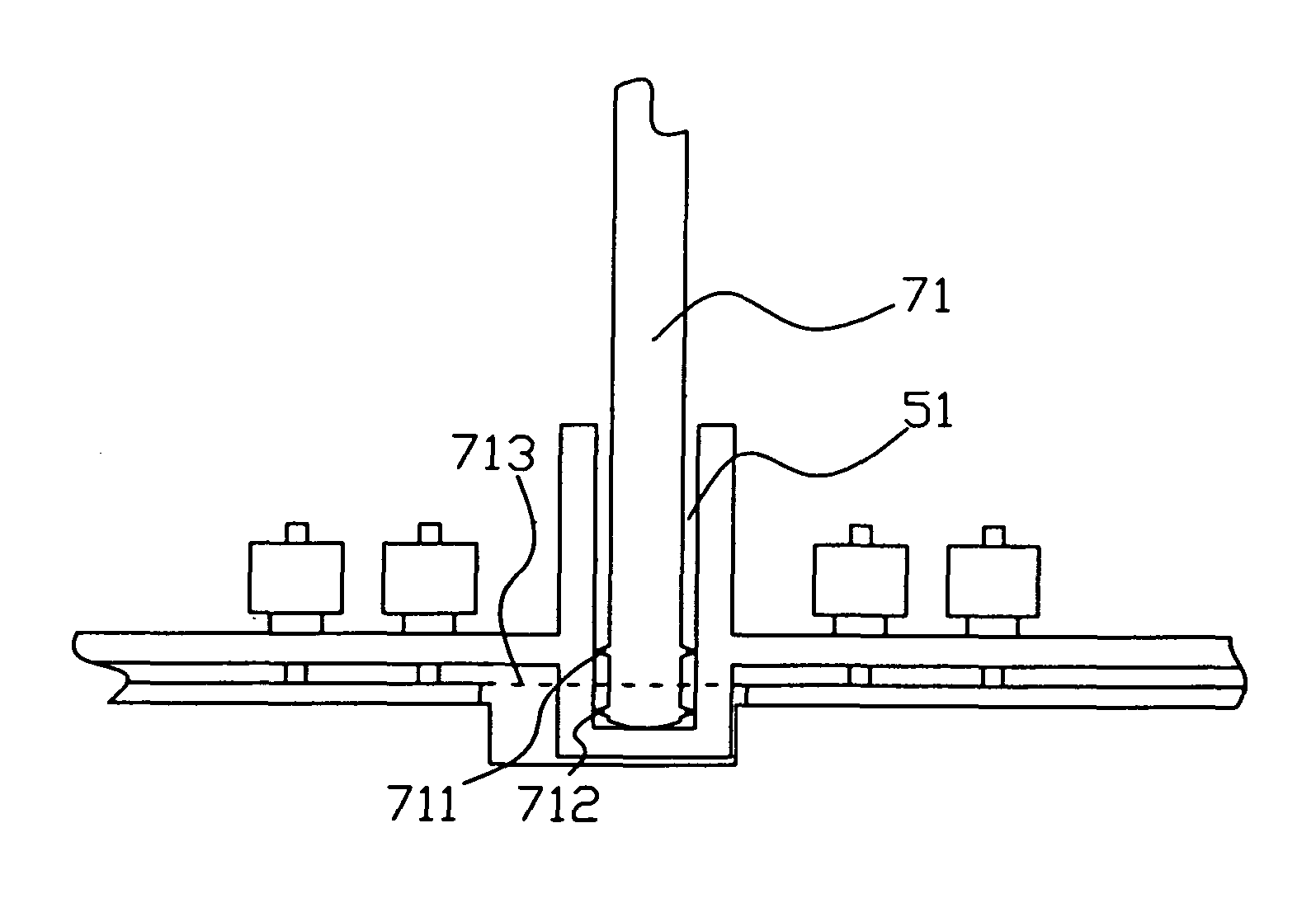
[0070]Please refer to FIGS. 9B and 9C. The second implementation of the present invention provides a projection section 711′ at the bottom end of the fixing rod 71′ with the upper and lower edges of the projection section 711′ forming the upper and lower contact portions 712′, 713′. The upper and lower contact portions 712′ and 713′ are respectively disposed above and below a contact plane 714′ between the end surface of the respective optical fiber and a polishing surface, and it is preferable that the upper and lower contact portions 711, 712 have an equal distance from the contact plane 714′; it can attain the same effect as the upper and lower contact portions 711 and 712 disposed at the bottom of the fixing rod 71 shown in FIG. 9B. The second implementation of the present embodiment can also be applied to other embodiments.

[0071]Please refer to FIGS. 9B and 9D. The third implementation of the first embodiment of the present invention is illustrated. A fixing groove 51′ for rece...

fifth embodiment

[0076]In the process of polishing, the holder of the fifth embodiment allows the fixing rod 781 to keep parallel to the inner wall of the fixing groove 671, and allows the main body 78 to keep parallel to the polishing surface 64 with the upper and lower contact portions 782, 783 contacting with the inner wall of the fixing groove 671 such that the pressure acting on the end surface of each optical fiber 63 is uniform. Hence, it becomes applicable for polishing the end surfaces of a large number of optical fibers simultaneously.

[0077]Please refer to FIGS. 13 and 14. The sixth preferred embodiment of the present invention is illustrated. The structure of the holder shown in FIG. 14 is almost the same as the holder shown in FIG. 13 except that the inner wall of a fixing groove 681 of a framework 68 is provided with one set of upper and lower contact portions 682 and 683 projecting toward the groove instead of a fixing rod 791 of a main body 79 being provided with the upper and lower c...


PUM


Abstract

A holder for supporting an end surface of a workpiece during polishing comprises a main body and a framework which are respectively provided with fixing portions corresponding to each other; at least one of the two fixing portions has at least one set of upper and lower contact portions, and the upper and the lower contact portions on each set are respectively disposed above and below a contact plane formed between the end surface of the workpiece and a polishing surface; when the upper and lower contact portions and another one of the fixing portions one another, the main body is capable of keeping parallel to the polishing surface, and the pressure acting on the end surface of each workpiece is capable of being approximately uniform. Hence, the number of end surfaces of the optical fibers can be increased tremendously during polishing so as to enhance the polishing speed and quality.

Description

BACKGROUND OF THE INVENTION[0001]1. Field of the Invention[0002]The present invention relates to an apparatus for polishing an end surface of a workpiece, and more particularly, to a holder for supporting an end surface of an optical fiber during a polishing being performed.[0003]2. Description of Related Art[0004]The optical fiber communication has been an indispensable communication tool at present and it will be in the future too. The main structure of an optical fiber connecter used for the optical fiber communication, as FIG. 1 shows, is constituted by an optical fiber 11 passing through a ferrule 12 and then being adhered to the ferrule 12 with an adhesive. The ferrule 12 can be made from plastic, glass or ceramics. A projecting spherical surface 121 of the end surface of the ferrule 12 is pressed by an elastic polishing surface and formed by way of coarse grinding, fine grinding and polishing respectively. The finished projecting spherical surface 121 must be worked as a flaw...

Claims


Application Information

Patent Timeline
Patent Type & Authority Patents(United States)
IPC IPC(8): B24B7/00B24B19/00B24B41/06
CPCB24B19/226
Inventor LING, KOW-JE
Owner LING KOW JE
Why Eureka
Try Eureka