High-efficiency vehicular transmission

a transmission and high-efficiency technology, applied in hybrid vehicles, gearing, transportation and packaging, etc., can solve the problems of driving warranty cost, affecting customer satisfaction, and affecting the performance of the transmission, so as to improve the transmission

Inactive Publication Date: 2011-05-17
MEANS IND INC
View PDF17 Cites 113 Cited by
  • Summary
  • Abstract
  • Description
  • Claims
  • Application Information

AI Technical Summary

Benefits of technology

[0047]An object of at least one embodiment of the present invention is to provide an improved vehicular transmission which eliminates the need for a torque converter, oil pump, valve body, and friction clutches. The transmission does not use any hydraulic circuits for power transmission.
[0064]The electric motor may soften one-way clutch engagements to obtain lower NVH in response to a control signal.

Problems solved by technology

The slipping of the torque converter is also a significant source of loss and the open friction elements in the transmission provide drag and thus losses also.
Another disadvantage is the complexity of these components.
Clutches, pumps, torque converters, and valve bodies are the most likely components to have issues and thus drive warranty cost and negatively impact upon customer satisfaction.
These components also tend to be the most expensive components in the transmission.

Method used


Image

  • High-efficiency vehicular transmission
  • High-efficiency vehicular transmission
  • High-efficiency vehicular transmission

Examples


Embodiment Construction

)

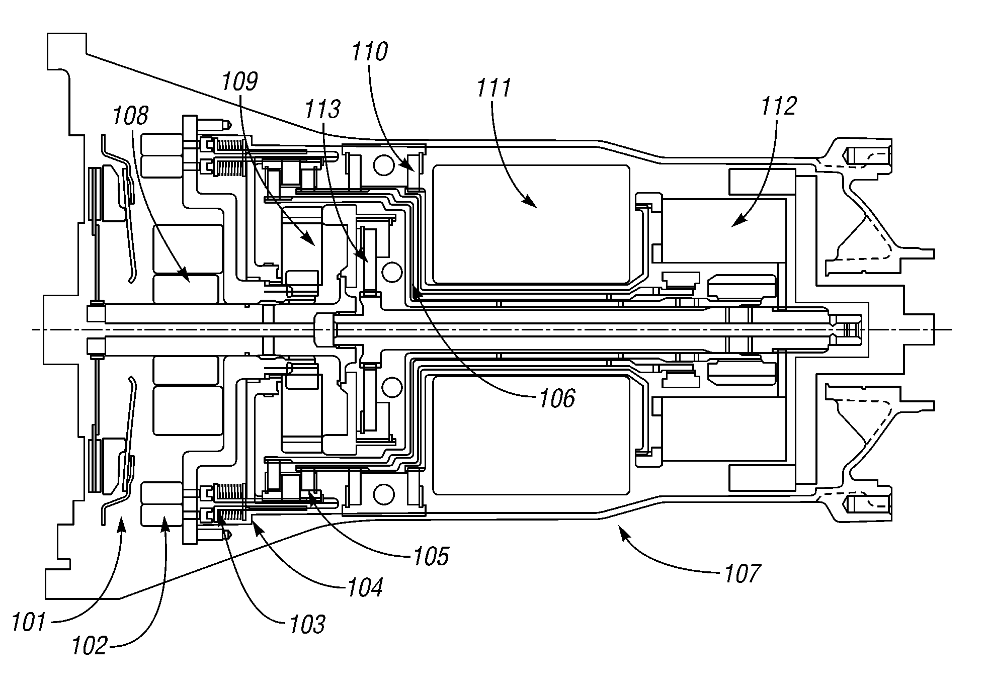
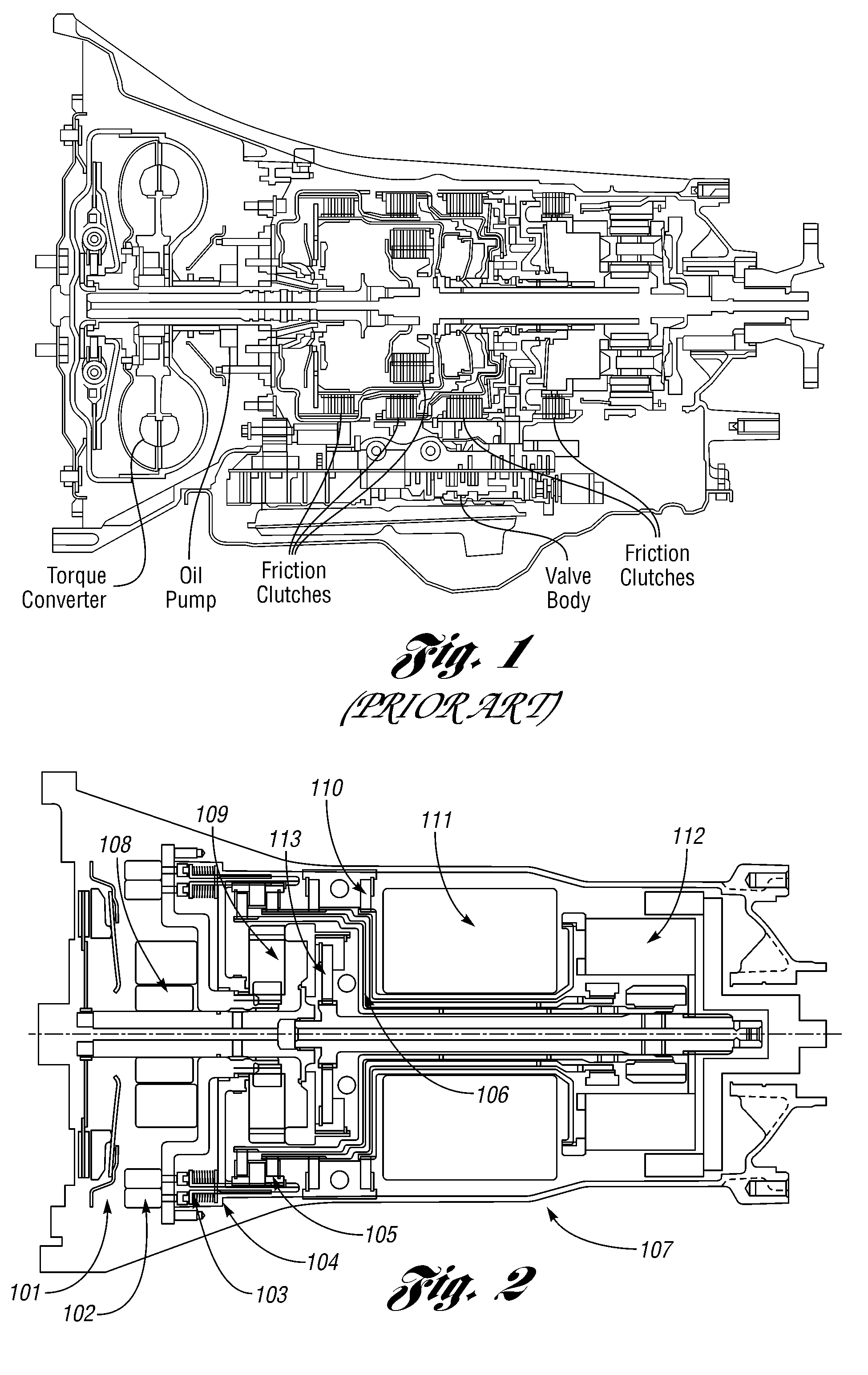
[0074]Referring now to FIG. 2, there is illustrated a sectional view of a vehicular step ratio transmission, generally indicated at 10, constructed in accordance with at least one embodiment of the present invention. The transmission 10 uses a Lepelletier 6-speed power flow to illustrate how at least one embodiment of the invention operates. The '352 patent discloses such a multi-speed automatic transmission. In one embodiment disclosed in the '352 patent, the transmission 10 includes a simple planetary gear set and a compound planetary gear set of the Ravigneaux type.

[0075]The following is a list of some of the parts shown in FIG. 2:[0076]101 Luk ball ramp clutch[0077]102 Electric stepper motors for “A” and “B” clutches[0078]103 Apply bearing[0079]104 Return spring[0080]105“A” and “B” OWC module[0081]106“E” clutch solenoid / stepper motor[0082]107 Case / housing[0083]108 Transformer for “E” clutch[0084]109 Front under-drive planetary gear set[0085]110“C” and “D” OWC module[0086]111 El...


PUM


Abstract

A high-efficiency vehicular transmission is provided. The transmission includes a transmission housing, a set of torque delivery elements which include first and second elements supported for rotation within the housing and an electric motor for changing angular velocity of at least one of the elements in response to an electrical signal during a shift to obtain a desired transmission ratio. At least one non-friction controllable coupling assembly has a coupling state for coupling the first element to either the second element or the housing and an uncoupling state for uncoupling the first element from either the second element or the housing, respectively. The at least one coupling assembly is non-hydraulically controlled to change state to maintain the desired transmission ratio.

Description

CROSS-REFERENCE TO RELATED APPLICATIONS[0001]This application claims the benefit of U.S. provisional patent application Ser. No. 60 / 998,773 filed Oct. 12, 2007 and entitled “Synch Shift Transmission.”BACKGROUND OF THE INVENTION[0002]1. Field of the Invention[0003]This invention relates to vehicular transmissions such as step ratio automatic transmissions.[0004]2. Background Art[0005]Today's step ratio automatic transmissions use hydraulics to power the ratio change, dampen NVH, power coupling / decoupling, and providing lubrication and cooling. This is achieved with the use of a torque converter (for coupling / decoupling power, multiplying torque, and NVH dampening), an oil pump, valve body (or hydraulic logic), and friction-type clutches (bands and frictions as shown in FIG. 1).[0006]The torque converter provides fluid coupling between the engine and the transmission. A typical torque converter comprises: an impeller which is rigidly connected to the torque converter housing; a turbin...

Claims


Application Information

Patent Timeline
Patent Type & Authority Patents(United States)
IPC IPC(8): B60W10/08
CPCB60K6/365B60W10/08B60W10/115F16H3/725B60K6/48Y10T477/26B60L2240/421B60W20/00B60W2710/081F16H2200/0052F16H2200/2007F16H2200/2023F16H2200/2043F16H2200/2097Y02T10/6221Y02T10/642Y02T10/62Y02T10/64
Inventor KIMES, JAMES W.
Owner MEANS IND INC
Why Eureka
Try Eureka