Sensorless controlling apparatus of brushless motor

a brushless motor and sensorless technology, applied in the direction of motor/generator/converter stopper, dynamo-electric gear control, motor/generator/converter stopper, etc., can solve the problem of high computational processing capability of high-cost cpu, large computation load when loop processing is performed for frequently estimating angle, etc. problem, to eliminate the need for changing a computation processing program, the effect of low-cost cpu

Inactive Publication Date: 2011-05-17
JTEKT CORP
View PDF16 Cites 19 Cited by
  • Summary
  • Abstract
  • Description
  • Claims
  • Application Information

AI Technical Summary

Benefits of technology

[0006]It is therefore an object of the invention to provide a sensorless controlling apparatus of a brushless motor for making it possible to use a low-cost CPU and eliminate the need for changing a computation processing program.
[0011]According to the configuration, the sensorless controlling apparatus includes the speed calculator for calculating the rotor speed, the angle calculator for calculating the rotor angle at a predetermined time interval, and the angle controller for calculating the correction angle based on the current value of the d-axis current, thereby controlling the rotor angle. The angle calculator calculates the rotor angle at the predetermined time interval by using the correction angle calculated by the angle controller, the rotor speed calculated by the speed calculator, the predetermined time interval, and the rotor angle calculated by the angle calculator at a predetermined time. Consequently, the rotor angle calculated by the angle calculator can be converged on the true angle of the rotor and sensorless vector control can be performed by performing simple computation with small computation load without using a motor model. The computation load decreases and the need for using a high-performance and high-cost CPU is eliminated. Therefore, a low-cost CPU can be used. Further, the rotor angle can be converged on the true angle of the rotor without using a motor model, so that it is not necessary to change the computation processing program corresponding to the brushless motor to be controlled. Therefore, the controlling apparatus high in general versatility can be provided.
[0017]According to the configuration, the angle calculator calculates the rotor angle θk+1 at the predetermined time interval by computing the expression. Thus, the rotor angle can be calculated by performing simple computation with small computation load.
[0020]According to the configuration, if the speed calculator determines that the rotor has rotated the predetermined angle based on the rotor angle calculated by the angle calculator, the speed calculator calculates the rotor speed and also calculates the rotor speed ω by computing the expression. Thus, the rotor speed can be calculated based on the rotor angle calculated by the angle calculator and can be calculated by performing simple computation with small computation load.
[0021]According to the invention, there can be provided a sensorless controlling apparatus for a brushless motor for making it possible to use a low-cost CPU and further eliminate the need for changing a computation processing program corresponding to the brushless motor to be controlled.

Problems solved by technology

However, in the related art described above, a motor model needs to be used to estimate the angle of the rotor of a brushless motor and the computation load is large.
That is, since the angle of the rotor is estimated using inductance and resistance of a stator coil forming a part of the brushless motor, the computation load when loop processing is performed for frequently estimating the angle is large.
Consequently, a high-cost CPU having a high-performance computation processing capability needs to be used; this is a problem.
Since the motor model of inductance, resistance, etc., of a coil forming a part of a brushless motor varies from one brushless motor to another, it is necessary to change a computation processing program to estimate the angle depending on the brushless motor to be controlled; this is a problem.

Method used


Image

  • Sensorless controlling apparatus of brushless motor
  • Sensorless controlling apparatus of brushless motor
  • Sensorless controlling apparatus of brushless motor

Examples


Embodiment Construction

[0025]Referring now to the accompanying drawings, there is shown a specific embodiment of the invention. The speed in Specification is the angular speed indicating the rotating speed.

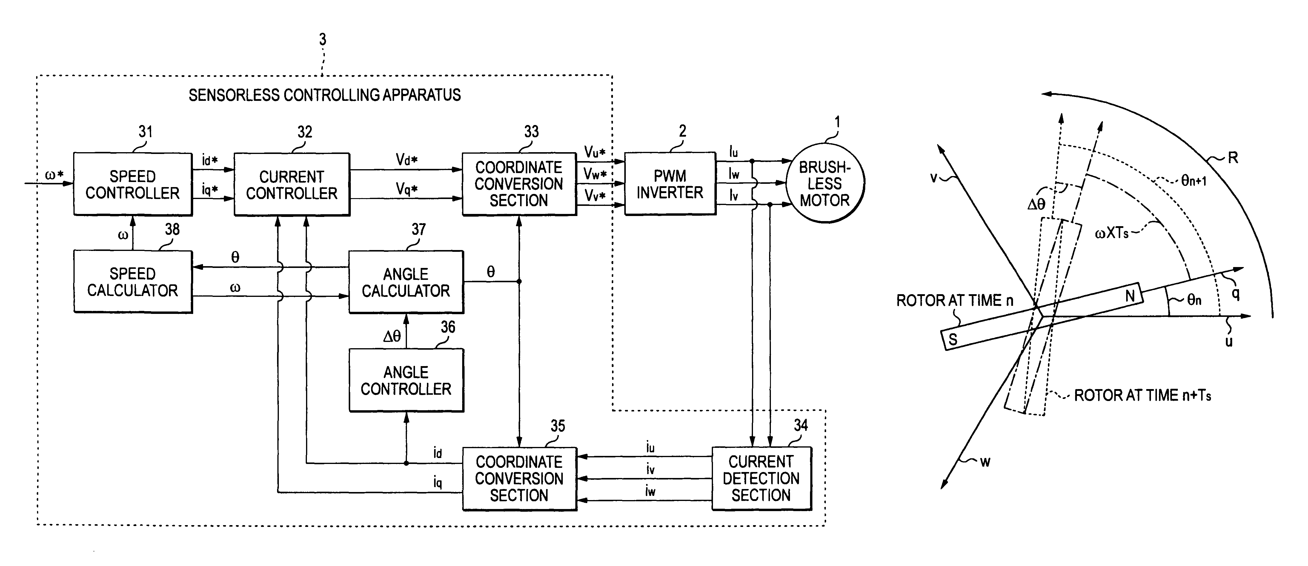
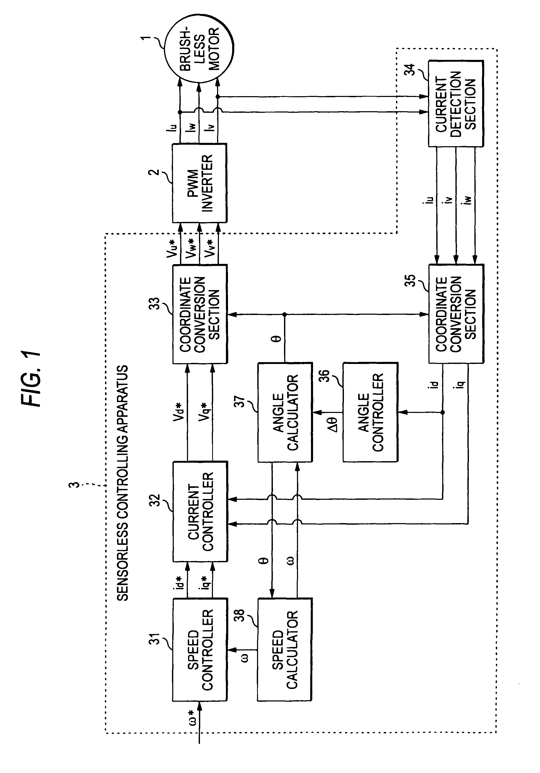
[0026]A motor drive control system according to the embodiment of the invention includes a brushless motor 1 (simply, “motor 1”), a PWM inverter 2 for driving the motor 1, and a sensorless controlling apparatus 3 (simply, “controlling apparatus 3”) for controlling the motor 1 by controlling the PWM inverter 2.

[0027]The motor 1 is made up of a rotor (not shown) having a permanent magnet and a stator (not shown) having stator coils (not shown) of a plurality of phases of a U phase, a V phase, and a W phase (namely, three phases) for generating a rotating magnetic field to rotate the rotor.

[0028]The PWM inverter 2 converts DC power supplied from a power supply section (not shown) of a battery, etc., into 3-phase AC power and commutates energization of the stator coils of three phases of the motor 1 in orde...


PUM


Abstract

A sensorless controlling apparatus for controlling a brushless motor includes a speed calculator for calculating speed of a rotor ω, an angle calculator for calculating rotor angle θ at a predetermined time interval, and an angle controller for calculating correction angle Δθ based on the current value of a d-axis current (d-axis current value id), thereby controlling the rotor angle θ. The angle calculator uses the correction angle Δθ calculated by the angle controller, the speed ω calculated by the speed calculator, a predetermined time, and the rotor angle θ calculated by the angle calculator at a predetermined time to calculate the rotor angle at the predetermined time interval. Thus, the rotor angle θ calculated by the angle calculator is converged on the true angle of the rotor.

Description

BACKGROUND OF THE INVENTION[0001]This invention relates to a sensorless controlling apparatus of a brushless motor for performing vector control by calculating the angle of a rotor using a d-axis current.[0002]Generally, a controlling apparatus for performing vector control to control drive of a brushless motor is known. In the vector control, current values of three phases in a fixed coordinate system (namely, a coordinate system made up of a u axis, a v axis, and a w axis each forming an angle of 120 degrees and crossing at one point) are converted into currents of two phases (namely, d-axis current and q-axis current) in a rotating coordinate system (namely, a coordinate system made up of a d-axis indicating the magnetic flux direction of a field pole and a q-axis orthogonal to the d-axis) and the currents of two phases are used for controlling.[0003]A sensorless controlling apparatus for performing the vector control and estimating the angle (position, phase) of a rotor without ...

Claims


Application Information

Patent Timeline
Patent Type & Authority Patents(United States)
IPC IPC(8): H02P6/00H02P21/00H02P6/06H02P6/08H02P6/16H02P6/18H02P21/18H02P21/24H02P21/28H02P23/14H02P23/16H02P25/022H02P27/04
CPCH02P21/0035H02P6/16H02P21/22
Inventor OKUMURA, SHIGEKAZU
Owner JTEKT CORP
Why Eureka
Try Eureka