
Output voltage controller for AC vehicle generator

a technology for ac vehicle generators and output voltage controllers, which is applied in the direction of electric generator control, dynamo-electric converter control, vehicle energy devices, etc., can solve the problems of undesirable effects on battery and other electrical loads, and achieve the effect of reducing the field coil easily

Inactive Publication Date: 2011-05-17
MITSUBISHI ELECTRIC CORP
View PDF61 Cites 10 Cited by
  • Summary
  • Abstract
  • Description
  • Claims
  • Application Information

AI Technical Summary

Benefits of technology

The invention proposes an improved output voltage controller for an AC vehicle generator that can reduce the switching surge voltage without complicating the voltage adjustment circuit. The controller includes a rectifier, excitation circuit, semiconductor switch element, voltage adjustment circuit, inductor, and transient voltage absorption means. The transient voltage absorption means absorbs a transient voltage generated in the inductor in association with the switching of the semiconductor switch element between ON and OFF. This reduces the switching surge voltage generated in the field coil without the need for a special slope generation circuit in the voltage adjustment circuit.

Problems solved by technology

The switching surge voltage varies the rectified output voltage, so that the battery and other electrical loads are undesirably affected.

Method used


Image

  • Output voltage controller for AC vehicle generator
  • Output voltage controller for AC vehicle generator
  • Output voltage controller for AC vehicle generator

Examples


first embodiment

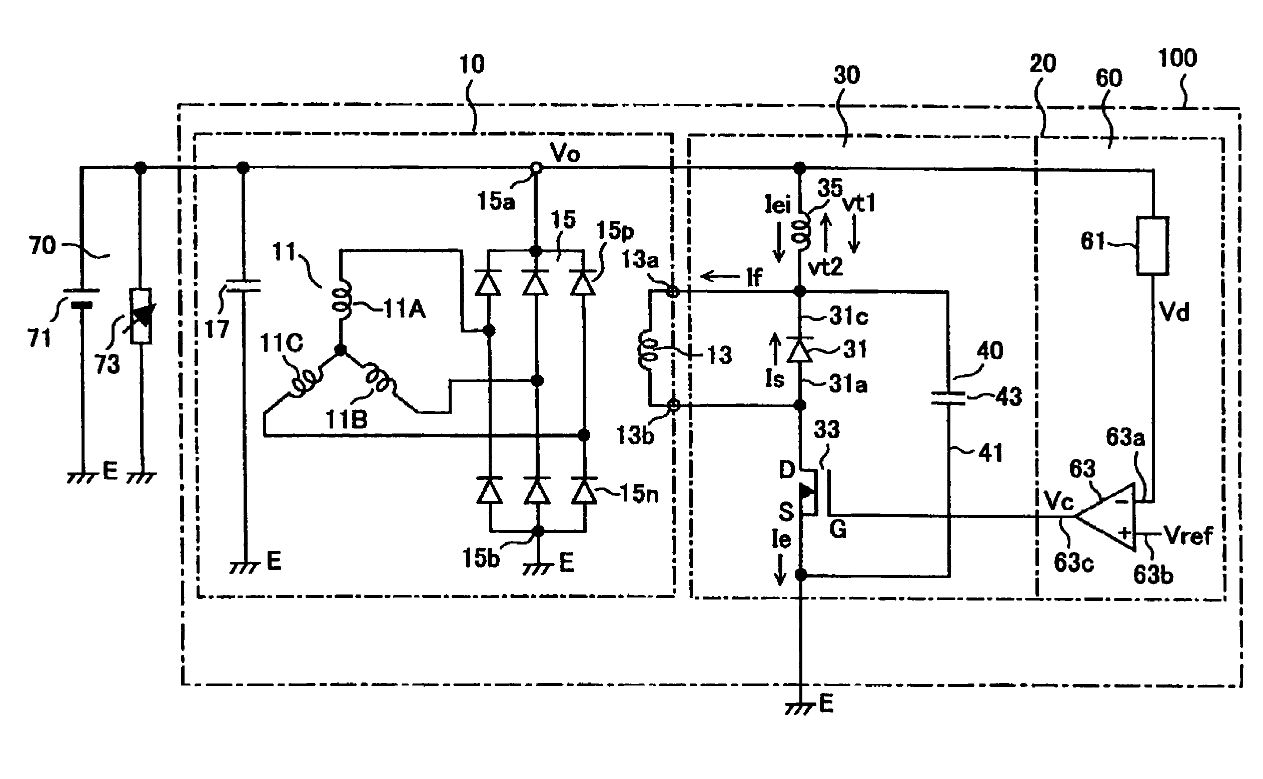
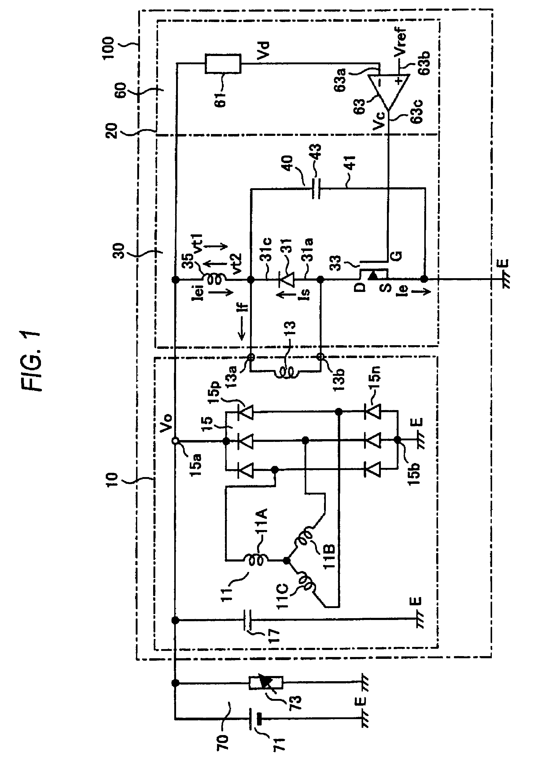
[0011]FIG. 1 is an electric circuit diagram showing a first embodiment of an output voltage controller for an AC vehicle generator according to the invention.

[0012]The output voltage controller 100 for an AC vehicle generator of the first embodiment includes an AC vehicle generator 10 and a voltage control unit 20, and supplies electricity to a load circuit 70.

[0013]The AC vehicle generator 10 is an AC generator with a rectifier built therein and includes an armature coil 11, a field coil 13, a rectifier 15, and a capacitor 17. The AC vehicle generator 10 is, for example, a rotating-field type three-phase AC generator, and the armature coil 11 includes three-phase coils 11A, 11B, and 11C and is configured as a stator. The three-phase coils 11A, 11B, and 11C are connected in a three-phase star configuration, but may be connected in a three-phase delta configuration in some cases. The field coil 13 is configured as a rotor, and provides a rotating magnetic field to the armature coil 1...

second embodiment

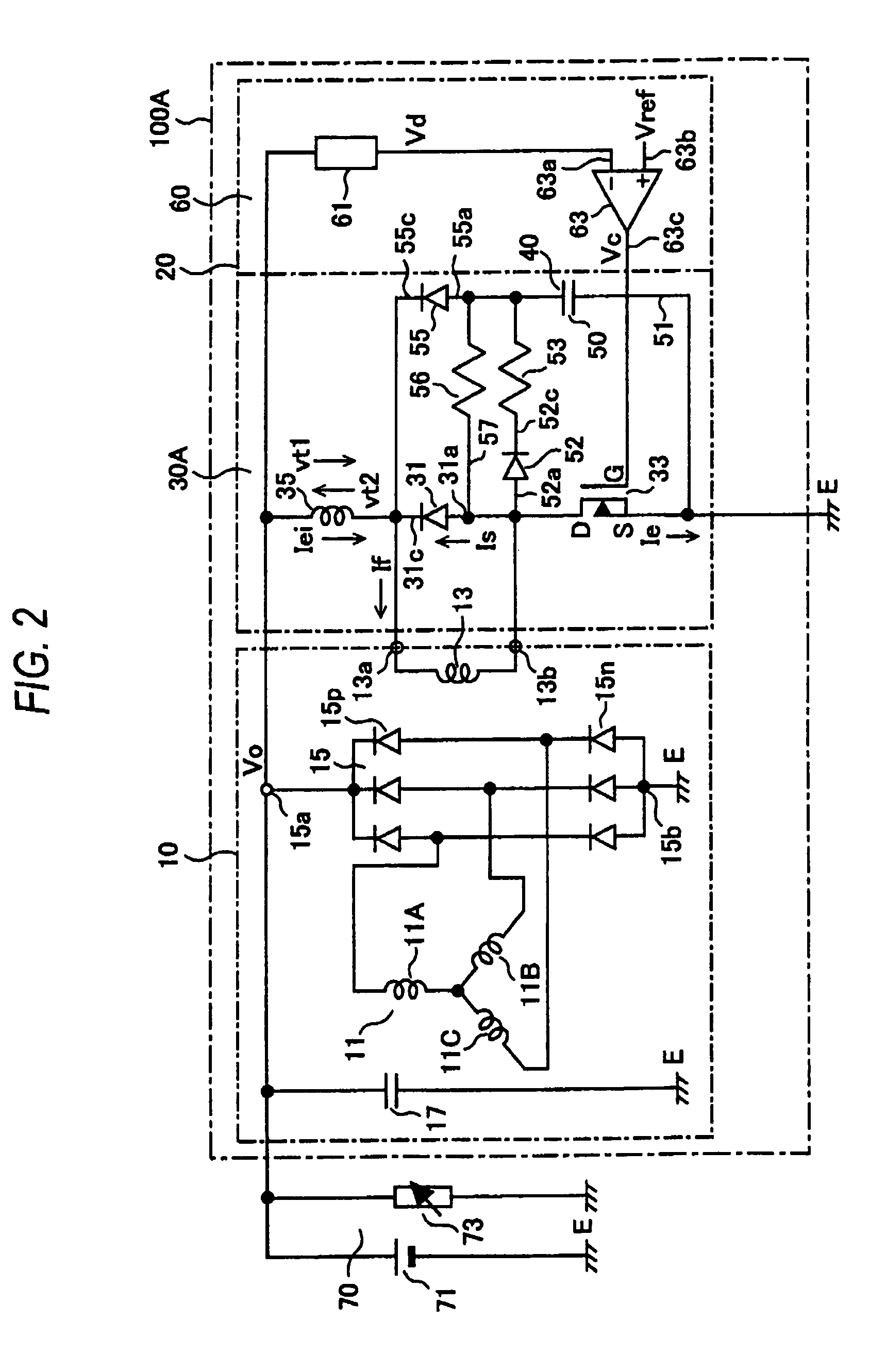
[0040]FIG. 2 is an electric circuit diagram showing a second embodiment of an output voltage controller for an AC vehicle generator according to the invention.

[0041]In the output voltage controller 100A for an AC vehicle generator according to the second embodiment, the voltage control unit 20 includes an excitation circuit 30A, which is a modified version of the excitation circuit 30 in the first embodiment, and the voltage adjustment circuit 60. In the second embodiment, the excitation circuit 30A includes the circulation element 31, the semiconductor switch element 33, and the inductor 35 in the first embodiment as well as a capacitor 50, a first diode 52, a first resistor 53, a second diode 55, and a second resistor 56. The capacitor 50 forms transient voltage absorption means 40 in the second embodiment. Other portions are configured in the same manner as the first embodiment.

[0042]In the excitation circuit 30A of the second embodiment, the capacitor 50 is disposed in a branch ...


PUM


Abstract

An output voltage controller for an AC vehicle generator is proposed. The output voltage controller can easily suppress variation in rectified output voltage due to a switching surge without using a slope generation circuit in a voltage adjustment circuit. An excitation circuit that excites a field coil 13 includes a circulation element 31, a semiconductor switch element 33, an inductor 35, and transient voltage absorption means 40. The circulation element 31 is connected in parallel to the field coil 13. The semiconductor switch element 33 is connected in series with the field coil 13 and turned on and off by a voltage adjustment circuit 60. The inductor 35 is connected in series with the field coil 13 and the semiconductor switch element 33. The transient voltage absorption means 40 absorbs a transient voltage generated in the inductor 35 in association with the switching of the semiconductor switch element 33 between ON and OFF.

Description

TECHNICAL FIELD[0001]The present invention relates to an output voltage controller for an AC vehicle generator equipped in a vehicle such as an automobile.BACKGROUND ART[0002]An AC vehicle generator of this type includes an armature coil and a field coil, and is driven by a motor, such as an engine equipped in the vehicle, so that an AC output voltage is generated in the armature coil. The AC vehicle generator is connected to a rectifier, which produces a rectified output voltage obtained by rectifying the AC output voltage generated in the armature coil in the AC vehicle generator. The rectified output voltage charges a battery equipped in the vehicle and supplies electricity to various electrical loads in the vehicle.[0003]The rectified output terminal of the rectifier is connected to an excitation circuit that excites the field coil. The excitation circuit is connected to a semiconductor switch element that is disposed in series with the field coil. The semiconductor switch eleme...

Claims


Application Information

Patent Timeline
Patent Type & Authority Patents(United States)
IPC IPC(8): H02P11/00H02P9/00H02H7/06F02B67/06F02B61/04B61D43/00H02P9/26
CPCH02P9/305H02P29/024H02P9/48H02P2101/45H02P29/0241H02J7/243
Inventor NISHIMURA, SHINJI
Owner MITSUBISHI ELECTRIC CORP
Learn More