Image forming optical system

an optical system and image technology, applied in optics, instruments, diffraction gratings, etc., can solve the problems of lager chromatic aberration, astigmatism, angle of incidence, and prevent efficient image forming, so as to reduce spherical aberration, reduce field curvature, and increase resolution

Active Publication Date: 2011-05-17
NALUX CO LTD
View PDF10 Cites 11 Cited by
  • Summary
  • Abstract
  • Description
  • Claims
  • Application Information

AI Technical Summary

Benefits of technology

[0005]Accordingly, there are needs for a compact image forming optical system in which angles of incidence to the image plane of the solid-state image sensor are made smaller and chromatic aberration, astigmatism, field curvature and distortion are reduced.
[0007]In the image forming optical system according to the first aspect of the invention, four lenses respectively having positive power, negative power, positive power and negative power are advantageously combined to reduce spherical aberration and therefore to increase resolution. Further, a combination of the third lens which is a positive meniscus lens convex to the image side and the fourth lens which is a negative meniscus lens convex to the object side can reduce a field curvature. Further, since the field stop is located on the object side of the image side plane of the first lens, a size of the optical system can be achieved.
[0008]By designing an image forming optical system such that the above-described relations (1) to (7) are satisfied, a compact image forming optical system in which angles of incidence to the image plane of the solid-state image sensor are small and chromatic aberration, astigmatism, field curvature and distortion are reduced can be realized.
[0010]In the image forming optical system according to the second aspect of the invention, four lenses respectively having positive power, negative power, positive power and negative power are advantageously combined to reduce spherical aberration and therefore to increase resolution. Further, a combination of the third lens which is a positive meniscus lens convex to the image side and the fourth lens which is a negative meniscus lens convex to the object side can reduce a field curvature. Further, since the field stop is located on the object side of the image side plane of the first lens, a size of the optical system can be achieved.
[0011]By designing an image forming optical system such that the above-described relations (1) and (5) to (8) are satisfied, a compact image forming optical system in which angles of incidence to the image plane of the solid-state image sensor are small and chromatic aberration, astigmatism, field curvature and distortion are reduced can be realized.

Problems solved by technology

However, these methods raise problems of an increase in angles of incidence to the image plane of the solid-state image sensor and lager chromatic aberration, astigmatism, field curvature and distortion.
An increase in angles of incidence to the image plane of the solid-state image sensor prevents efficient image forming on the solid-state image sensor.

Method used


Image

  • Image forming optical system
  • Image forming optical system
  • Image forming optical system

Examples


example 1

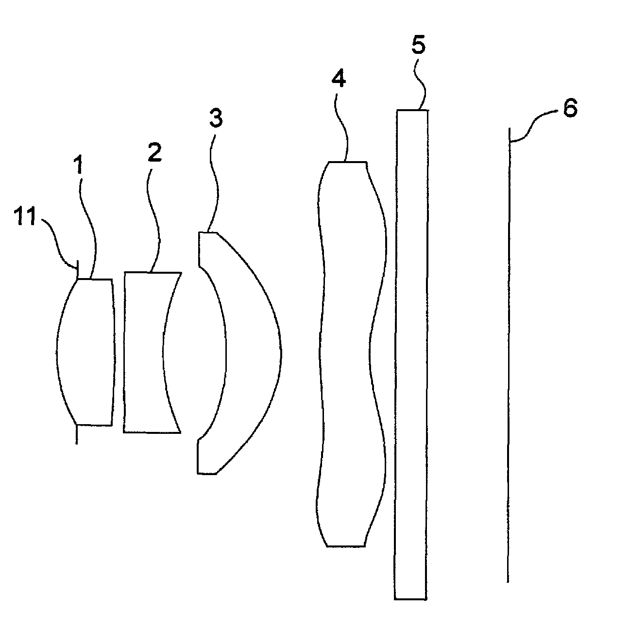
[0046]FIG. 1 shows a construction of an image forming optical system according to Example 1. The image forming optical system according to Example 1 includes a first lens 1, a second lens 2, a third lens 3 and a fourth lens 4 arranged from the object side to the image side. A field stop 11 is located on the object side of the image side plane of the first lens 1 and on the image side of the vertex of the object side plane of the first lens 1. Light having passed through the first lens 1, the second lens 2, the third lens 3 and the fourth lens 4 passes through a glass plate 5 and arrives at an image plane 6.

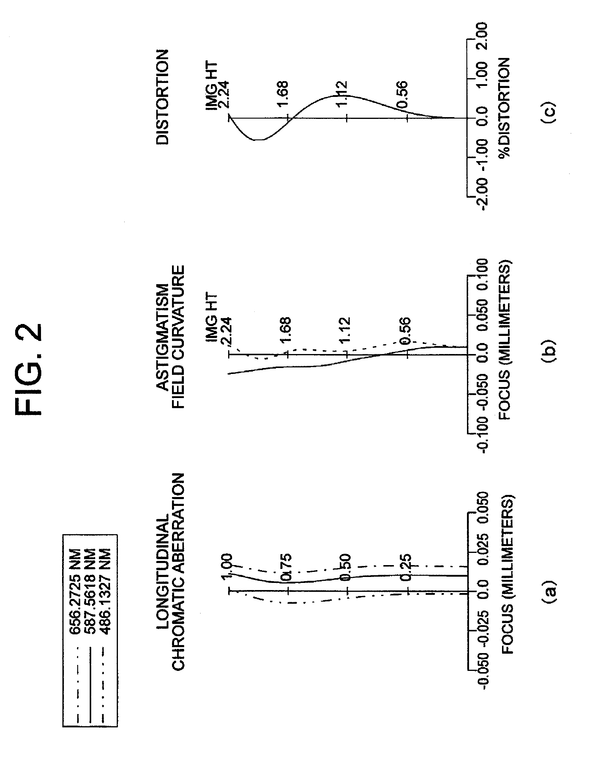
[0047]FIG. 2 shows aberrations of the image forming optical system according to Example 1. FIG. 2(a) represents longitudinal chromatic aberration. The horizontal axis of FIG. 2(a) represents a focal position in the optical axis direction. Unit is millimeter. The vertical axis of FIG. 2(a) represents a position in the field stop plane though which light passes. “0” on the vertical ...

example 2

[0053]FIG. 3 shows a construction of an image forming optical system according to Example 2. The image forming optical system according to Example 2 includes a first lens 201, a second lens 202, a third lens 203 and a fourth lens 204 arranged from the object side to the image side. A field stop 2011 is located on the object side of the image side plane of the first lens 201 and on the image side of the vertex of the object side plane of the first lens 201. Light having passed through the first lens 201, the second lens 202, the third lens 203 and the fourth lens 204 passes through a glass plate 205 and arrives at an image plane 206.

[0054]FIG. 4 shows aberrations of the image forming optical system according to Example 2. FIG. 4(a) represents longitudinal chromatic aberration. The horizontal axis of FIG. 4(a) represents a focal position in the optical axis direction. Unit is millimeter. The vertical axis of FIG. 4(a) represents a position in the field stop plane though which light pa...

example 3

[0060]FIG. 5 shows a construction of an image forming optical system according to Example 3. The image forming optical system according to Example 3 includes a first lens 301, a second lens 302, a third lens 303 and a fourth lens 304 arranged from the object side to the image side. A field stop 3011 is located on the object side of the image side plane of the first lens 301 and on the image side of the vertex of the object side plane of the first lens 301. Light having passed through the first lens 301, the second lens 302, the third lens 303 and the fourth lens 304 passes through a glass plate 305 and arrives at an image plane 306.

[0061]FIG. 6 shows aberrations of the image forming optical system according to Example 3. FIG. 6(a) represents longitudinal chromatic aberration. The horizontal axis of FIG. 6 (a) represents a focal position in the optical axis direction. Unit is millimeter. The vertical axis of FIG. 6(a) represents a position in the field stop plane though which light p...


PUM


Abstract

To provide a compact image forming optical system in which an incident angle to an imaging plane of a solid-state imaging device is small and whose chromatic aberration, astigmatism, field curvature, and distortion are reduced. An image forming optical system of a first embodiment of the present invention comprises four lenses arranged from the object side to the imaging plane side in order, that are a first lens that is a double-convex lens, a second lens that is a double-concave lens, a third lens that is a positive meniscus lens that is convex toward an image side, and a fourth lens that is a negative meniscus lens that is convex toward an object side. An aperture is placed closer to the object than the image side surface of the first lens. The image forming optical system of the first embodiment of the present invention satisfies the following equations, where fi is an absolute value of a focal length of i-th lens, f is an absolute value of a focal length of a whole optical system, vdi is Abbe's number of i-th lens, and TTL is a distance from the object side surface of the first lens, in the object side surface and an aperture side surface, to the imaging plane.0.425<f1 / f4<0.7  (1)25<vd2<28  (2)50<vd1,vd3,vd4<57  (3)0.595<f2 / f4<1.05  (4)1.5<f / f1<2.2  (5)f1<f3  (6)1.05<TTL / f<1.18  (7)

Description

TECHNICAL FIELD[0001]The present invention relates to an image forming optical system used for solid-state image sensors of digital cameras, cellular phones with a camera, scanners and the like.BACKGROUND ART[0002]As size reduction in digital cameras, cellular phones with a camera and the like is strongly required, size reduction in an image forming optical system used for these devices is also strongly required, Patent documents 1 and 2 disclose image forming optical systems used for solid-state image sensors of digital cameras, cellular phones with a camera, scanners and the like. In order to realize size reduction in an image forming optical system, there exists a method to reduce a distance from a lens to an image plane or a method to make the system wide-angle. However, these methods raise problems of an increase in angles of incidence to the image plane of the solid-state image sensor and lager chromatic aberration, astigmatism, field curvature and distortion. An increase in a...

Claims


Application Information

Patent Timeline
Patent Type & Authority Patents(United States)
IPC IPC(8): G02B9/34G02B9/60G02B5/18
CPCG02B13/004G02B9/34
Inventor SAKAGAMI, NORIHISA
Owner NALUX CO LTD
Why Eureka
Try Eureka