Control device for an actuator

a control device and actuator technology, applied in the field of actuators, can solve the problems of contact damage, b>5/b> being very likely to be directly collided by external objects, damage, etc., and achieve the effect of promoting the reliability of the control of the actuator

Active Publication Date: 2011-05-17
HIWIN MIKROSYST
View PDF1 Cites 12 Cited by
  • Summary
  • Abstract
  • Description
  • Claims
  • Application Information

AI Technical Summary

Benefits of technology

[0005]It is therefore a primary object of the present invention to provide a control device applicable to an actuator. The control device is an integration of a limit switch control unit and a voltage detection unit. The control device is inbuilt inside the actuator without any additional control circuit so that the appearance of the actuator is tidied and the reliability in the control of the actuator is promoted.

Problems solved by technology

As a result, a high current may flow through the contacts of the limit switches 4, 5 to cause damage of the contacts.
Also, after a long period of use, the contacts are liable to damage.
Moreover, the limit switches 4, 5 are very likely to be directly collided by external objects and damaged.
Therefore, as a whole, the layout of the external wires of the actuator 1′ is complicated.
This leads to increase of cost.
Such technique has poor reliability in voltage detection and control.
As a result, the actuator 1″ tends to operate too fast due to excessively high voltage.
After a long period of use, the actuating member 3″ may rush out from a predetermined travel and get damaged.
On the other hand, the actuator 1″ also may operate too slowly due to insufficient voltage.
In this case, after a long period of use, the motor 2″ may overheat to cause damage of components.

Method used


Image

  • Control device for an actuator
  • Control device for an actuator
  • Control device for an actuator

Examples


Embodiment Construction

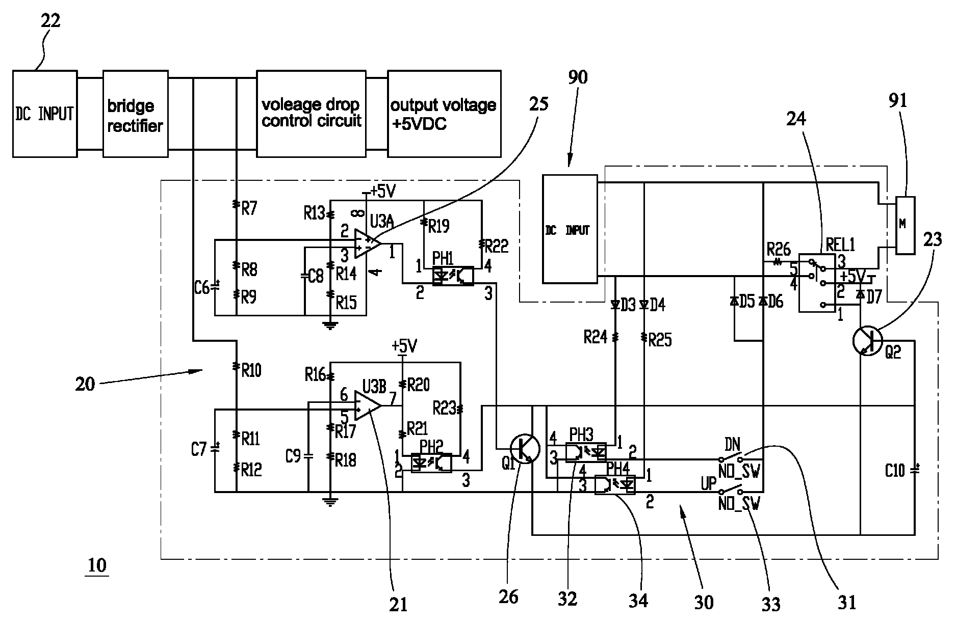
[0016]Please refer to FIG. 4. According to a first preferred embodiment, the control device 10 of the present invention is an integration of a limit switch control circuit and an input voltage detection circuit, which is applicable to an actuator 90. To speak more specifically, the control device 10 is inbuilt inside the actuator 90 in the form of a laminated circuit board to reduce the number of external wires of the actuator 90. It is unnecessary to arrange any additional external control circuit for controlling the limit switch and the detection of the input voltage range. Therefore, the wire layout can be simplified.

[0017]Please now refer to FIGS. 5 and 6. According to the above embodiment, the control device 10 includes a voltage detection unit 20 and a limit switch control unit 30.

[0018]The voltage detection unit 20 includes a low voltage input detection comparator 21 connected to a voltage input source 22 for detecting the input DC voltage. A first low-power switch 23 control...


PUM


Abstract

A control device applicable to an actuator and including a voltage detection unit and a limit switch control unit. The control device is inbuilt inside the actuator without any additional control circuit for the control of the limit switches and the detection of the input voltage range. The limit switches are used to limit the travel of an actuating member of the actuator so as to avoid collision of the mechanism. The voltage detection unit serves to detect the input voltage range to control the operation of the actuator. Accordingly, the mechanism or the motor is protected from damage due to excessively low or high input voltage. The limit switches are freely adjustable in position and protected from high current. Therefore, the contacts of the limit switches are not liable to damage and the lifetime of the limit switches is prolonged. The control device further has electronic brake effect.

Description

BACKGROUND OF THE INVENTION[0001]The present invention relates generally to an actuator, and more particularly to a control device applicable to an actuator. The control device is an integration of a limit switch control circuit and an input voltage detection circuit and has electronic brake effect.[0002]Most of the conventional limit switches applied to actuators pertain to hidden-type mechanical limit switches. FIG. 1 shows a conventional control device for an actuator 1. An actuating member 3 of the actuator 1 is driven by a motor 2 to move axially and reciprocally. Two mechanical limit switches 4, 5 are arranged in fixed positions to restrict the travel of the actuating member 3 within a range between two dead ends. In such conventional control device, the limit switches 4, 5 are hidden in the actuator so that it is impossible to adjust the positions of the limit switches 4, 5 in accordance with actual requirements. Moreover, the current that drives the motor 2 will directly flo...

Claims


Application Information

Patent Timeline
Patent Type & Authority Patents(United States)
IPC IPC(8): H01H47/00H02H3/24H01H51/22H02H3/00H02H3/20H01H9/00
CPCH02H7/09H02H7/0811H01H47/001H01H9/182
Inventor CHIANG, WEI-YUN
Owner HIWIN MIKROSYST
Why Eureka
Try Eureka