Method of selecting engine torque curves

a torque curve and engine technology, applied in the field of work vehicles, can solve the problems of short duration overload, high fuel consumption, and work vehicles such as combines also spend significant time at very light loads, and not return as good fuel economy

Active Publication Date: 2011-05-17
DEERE & CO
View PDF9 Cites 12 Cited by
  • Summary
  • Abstract
  • Description
  • Claims
  • Application Information

AI Technical Summary

Problems solved by technology

Such an overload may occur when clumps of moist material suddenly enter the threshing system causing higher, short duration overloads.
At the lower power end of the operational spectrum, work vehicles such as combines also spend significant time at very light loads, such as idling or going down hills.
In these cases, the high end torque curves that work well for performance, such as slug acceptance, high threshing loads, unloading grain on the go, etc., do not return as good of fuel economy as an engine torque curve optimized for a lower power level operation.
In addition, after treatment devices the are used to meet the Environmental Protection Agency's Tier 4 requirements need to operate at temperatures of around 300° Celsius or higher in order to regenerate the after treatment device, and these temperatures are typically not achieved when a high power torque curve equipped engine is operated at light loads.
In order to maintain the high temperature, additional fuel is burnt in the exhaust to elevate the temperature of the exhaust, thus exacerbating the fuel consumption problem.

Method used


Image

  • Method of selecting engine torque curves
  • Method of selecting engine torque curves
  • Method of selecting engine torque curves

Examples


Embodiment Construction

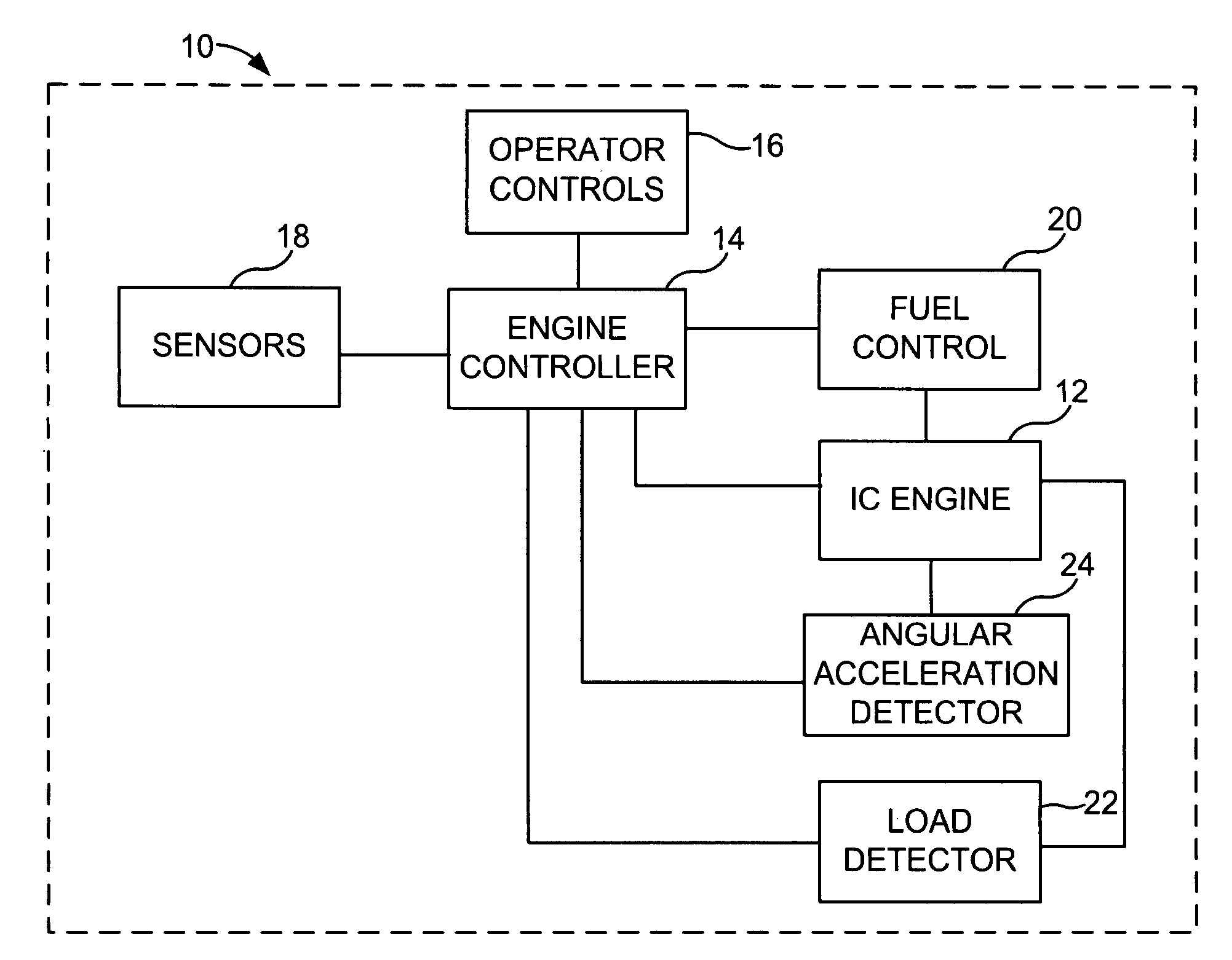
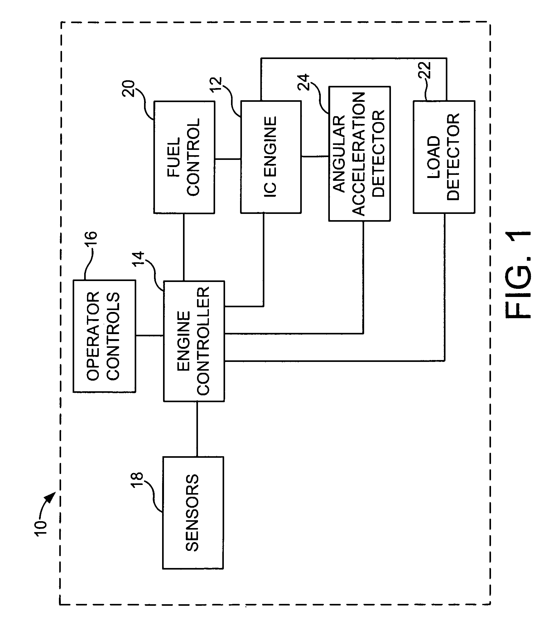
[0017]Referring now to the drawings, and more particularly to FIG. 1, there is shown a schematical view of an embodiment of the work vehicle system 10 of the present invention for operating an internal combustion (IC) engine 12. System 10 is part of a non-road work vehicle such as an agricultural tractor, combine, construction equipment, etc. IC engine 12 is configured as a diesel engine, but could also possibly be configured as a spark ignition engine. IC engine 12 is sized to accommodate the non-road vehicle.

[0018]Work vehicle system 10 further includes an engine controller 14, operator control 16, sensors 18, a fuel control system 20, a load detector 22, and an angle acceleration detector 24. Engine controller 14 is located on board the non-road vehicle and controls various electronically controllable functions of the vehicle. For example, in the event the non-road vehicle is configured as a combine, engine controller 14 can control the engine rpm and other functional aspects of ...


PUM


Abstract

A method of operating an internal combustion engine including the steps of detecting, determining, and switching. The detecting step detects a load on the engine. The determining step determines if the load is below a predetermined value. The switching step switches the engine to operate at a selected one of a plurality of torque power curves, dependent upon the determining step.

Description

FIELD OF THE INVENTION[0001]The present invention relates to work vehicles, and, more particularly to the selection of an engine torque curve for use by an engine of an agricultural harvester.BACKGROUND OF THE INVENTION[0002]An agricultural harvester, such as a combine, is a large machine used to harvest a variety of crops from a field. A combine includes a header at the front of the combine to cut the ripened crop in the field. A feeder housing supporting the header transfers the crop material into the combine for threshing. The threshing and separating assemblies within the combine remove grain from the crop material and transfer the clean grain to a grain tank for temporary holding. Crop material other than grain exits from the rear of the combine and is distributed upon the field. An unloading auger or conveyor transfers the clean grain from the grain tank to a transport vehicle.[0003]Off highway vehicles, such as combine harvesters, currently have a basic engine torque curve to...

Claims


Application Information

Patent Timeline
Patent Type & Authority Patents(United States)
IPC IPC(8): B60T7/12
CPCA01D41/127F02D41/021F02D41/1497F02D41/2422F02D2250/26F02D2200/1012F02D2250/18
Inventor SHEIDLER, ALAN D.SCHINDLER, RODNEY A.BURSIEK, CHRIS
Owner DEERE & CO
Why Eureka
Try Eureka