
Method and device for scan chain management of dies reused in a multi-chip package

a multi-chip package and scan chain technology, applied in the field of integrated circuit testing, can solve the problems of reducing the number of functional pins, requiring a large number of pins for a relatively large number of scan chains, and recurring problems such as the number of pins needed to execute tests

Inactive Publication Date: 2011-05-17
MARVELL INT TECH
View PDF11 Cites 20 Cited by
  • Summary
  • Abstract
  • Description
  • Claims
  • Application Information

AI Technical Summary

Benefits of technology

"The present invention relates to a method and apparatus for testing integrated circuits (ICs) in a multichip module (MCM) or system-in-package (SIP). The invention involves using a silicon interposer with logic to select any one of multiple dies for testing, and transmitting the test signals and results through the interposer. The testing can be done using a full-scan vector, a partial scan vector, an IC functional test vector, a direct test vector, a BIST self-test vector, or a test vector generated by Automatic Test Equipment. The testing can also be done by bypassing multiplexers. The invention provides a more efficient and effective way to test ICs in a multichip module or system-in-package."

Problems solved by technology

In all tests of a complex IC, a reoccurring problem is the number of pins needed to execute the tests.
First, since complex ICs have many cells, megacells and embedded blocks of logic, a large number of logic elements must be tested.
However, a relatively large number of scan chains generally requires a large number of pins.
Secondly, as ICs encompass whole electronic systems, the number of functional pins may actually decrease, as most of the interconnects previously found between ICs are absorbed into the single complex IC.
Scan testing multiple dies in a package such as a SIP can create problems, such as creating hidden scan chains that are not externally controllable or observable.
Further, once the dies are assembled in the SIP package, there is no easy, non-destructive way of testing the SIP package dies individually without using separate I / O pins for each device.
However, it may not be practical or possible to increase the pin count.
In any case, these less advantageous solutions add cost to the SIP package and / or are relatively time consuming; for example, it can take months to redesign dies and / or the SIP package in this way.

Method used


Image

  • Method and device for scan chain management of dies reused in a multi-chip package
  • Method and device for scan chain management of dies reused in a multi-chip package
  • Method and device for scan chain management of dies reused in a multi-chip package

Examples


Embodiment Construction

[0036]Reference will now be made in detail to the preferred embodiments of the invention, examples of which are illustrated in the accompanying drawings. While the invention will be described in conjunction with the preferred embodiments, it will be understood that they are not intended to limit the invention to these embodiments. On the contrary, the invention is intended to cover alternatives, modifications, and equivalents that may be included within the spirit and scope of the invention as defined by the appended claims. Furthermore, in the following detailed description of the present invention, numerous specific details are set forth in order to provide a thorough understanding of the present invention. However, it will be readily apparent to one skilled in the art that the present invention may be practiced without these specific details. In other instances, well-known methods, procedures, components, and circuits have not been described in detail so as not to unnecessarily o...


PUM


Abstract

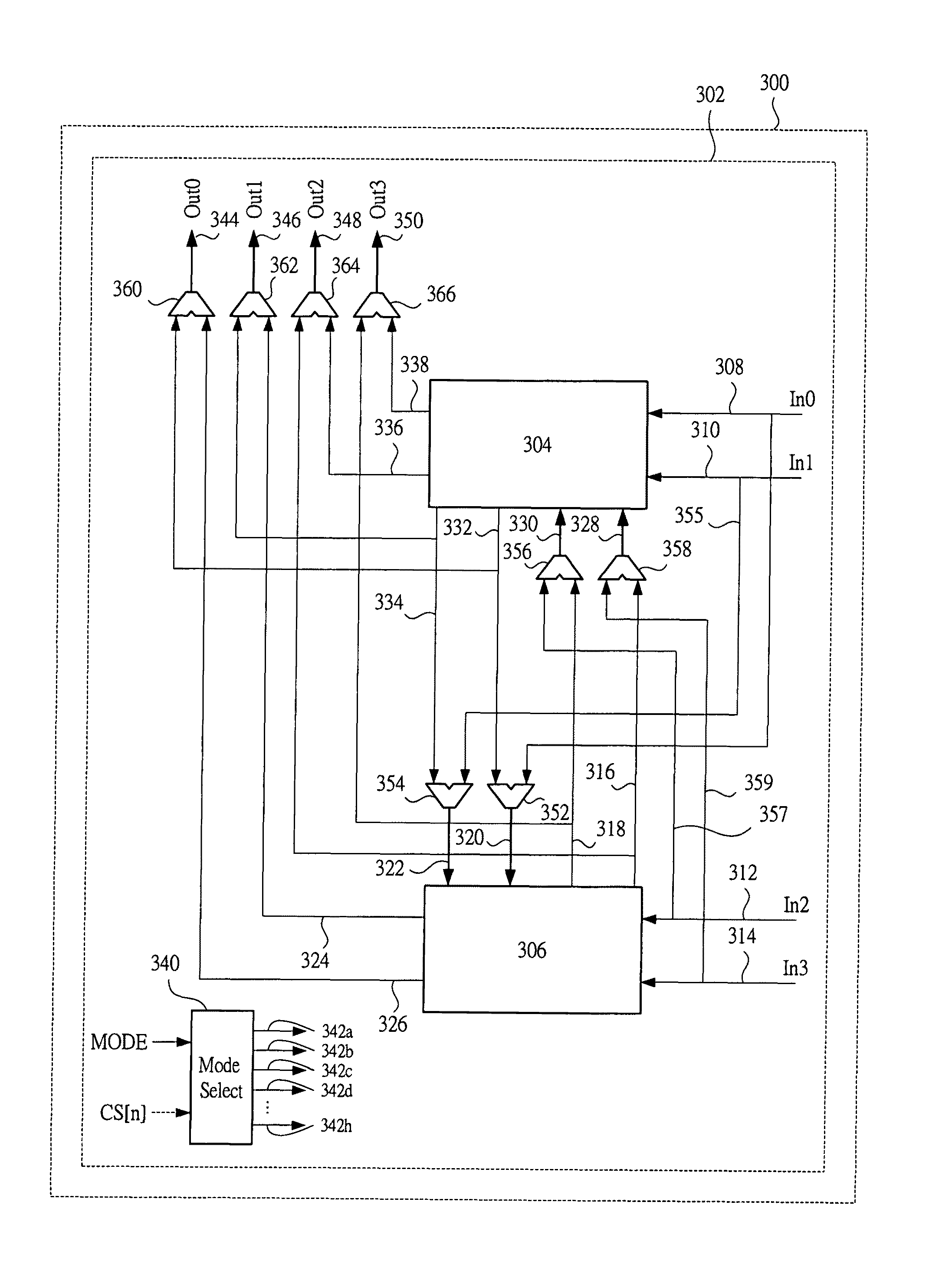
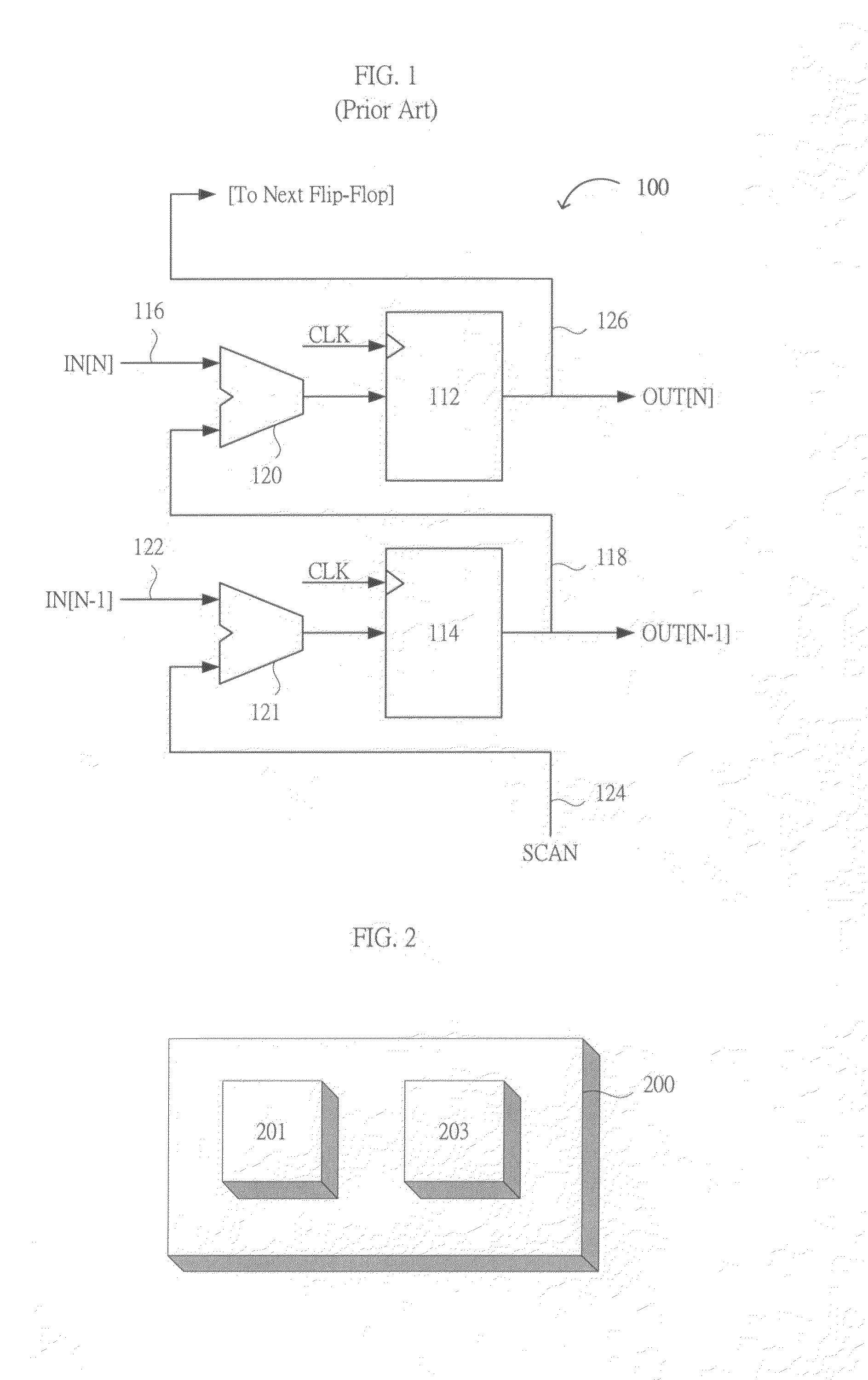
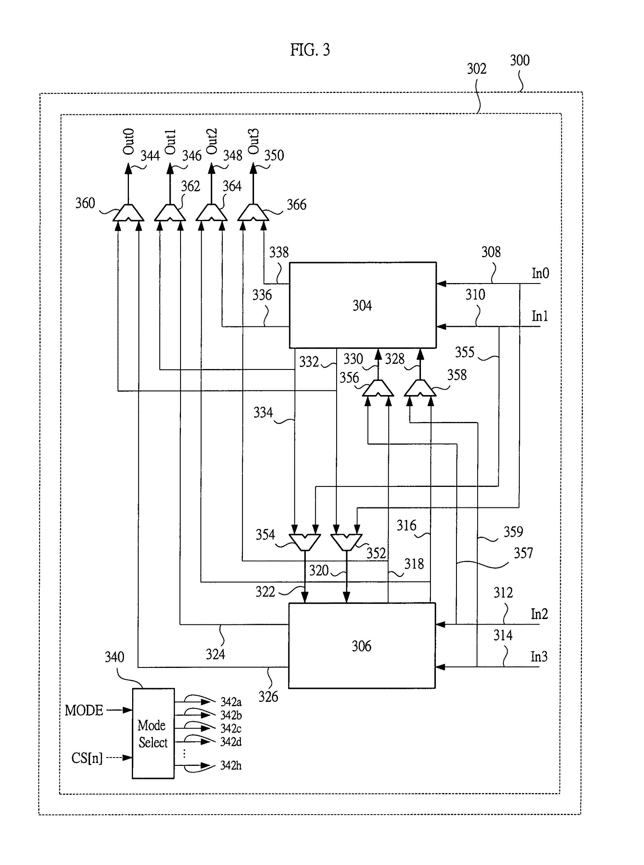
An apparatus and method for economical testing of dies in a multichip module. Internal I / O pins on a die are logically connected to external I / O pins of the multichip module through the use of a silicon interposer on which the dies are attached. Multiplexers on the interposer can select between the external pins of the multichip module and the internal pins of the dies. The silicon interposer can be economically manufactured using manufacturing technology having relatively a large feature size, such as is found in a relatively mature IC fabrication plant. Further, use of the present invention allows multichip modules to be tested for faults without the necessity of redesigning test circuitry or adding additional pins to the package.

Description

RELATED APPLICATIONS[0001]This application claims the benefit of U.S. Provisional Application No. 60 / 882,335, filed Dec. 28, 2006, and incorporated herein by reference in its entirety.FIELD OF THE INVENTION[0002]The present invention generally relates to the field of testing an integrated circuit (IC). More specifically, embodiments of the present invention pertain to circuits, systems, and methods for testing an IC in a packaged multichip module, such as a System-In-Package (SIP), and in particular scan chain testing of the same.DISCUSSION OF THE BACKGROUND[0003]Integrated circuits may be housed in a plurality of chip packages. A Multi-Chip Module (MCM) is a chip package that contains two or more dies mounted close together on a substrate base. The short traces between the chips can increase performance relative to individually packaged chips, such as by reducing noise that external traces between individual chip packages can produce, thereby allowing higher frequency of operation,...

Claims


Application Information

Patent Timeline
Patent Type & Authority Patents(United States)
IPC IPC(8): G01R31/28
CPCG01R31/318563G01R31/318513
Inventor BRIGGS, RANDALL D.
Owner MARVELL INT TECH
Learn More