Gas system for firearms

a gas system and firearm technology, applied in the direction of weapons, weapon components, etc., can solve the problems of inability to regulate the gas energy being transmitted to the piston, rapid deterioration and/or damage of the piston, and the gas actuating piston assembly of semi-automatic firearms can suffer, etc., to reduce or eliminate the damping effect of the return stroke of the piston

Inactive Publication Date: 2011-05-24
REM TML HLDG LLC
View PDF118 Cites 31 Cited by
  • Summary
  • Abstract
  • Description
  • Claims
  • Application Information

AI Technical Summary

Benefits of technology

[0009]A mechanical stop can be extended through the wall of the expansion housing for cooperatively engaging an elongated axial slot in the piston to thus limit the axial travel of the gas piston in the tubular housing. In other embodiments, the gas piston can be formed with a gas “shut-off” feature to limit the amount of gas diverted from the barrel through the gas ports to the piston. In another embodiment, the piston also can include a gas purge feature that evacuates the gas upon completion of a full stroke of the piston, thus reducing or eliminating the damping effect on the return stroke of the piston.

Problems solved by technology

Known gas actuating piston assemblies for semi-automatic firearms can suffer from numerous disadvantages, however, including the inability to regulate the gas energy being transmitted to the piston.
For example, the pressure of the diverted gases is often unequally distributed against the gas piston, thereby causing uneven movement of the piston that can result in rapid deterioration and / or damage to the piston.
Also, when lower power cartridges or shells are used, the pressure of the discharge gases sometimes is not sufficient to properly or fully actuate / drive the piston assembly, which can result in misfired or jammed shells or cartridges.

Method used


Image

  • Gas system for firearms
  • Gas system for firearms
  • Gas system for firearms

Examples


Embodiment Construction

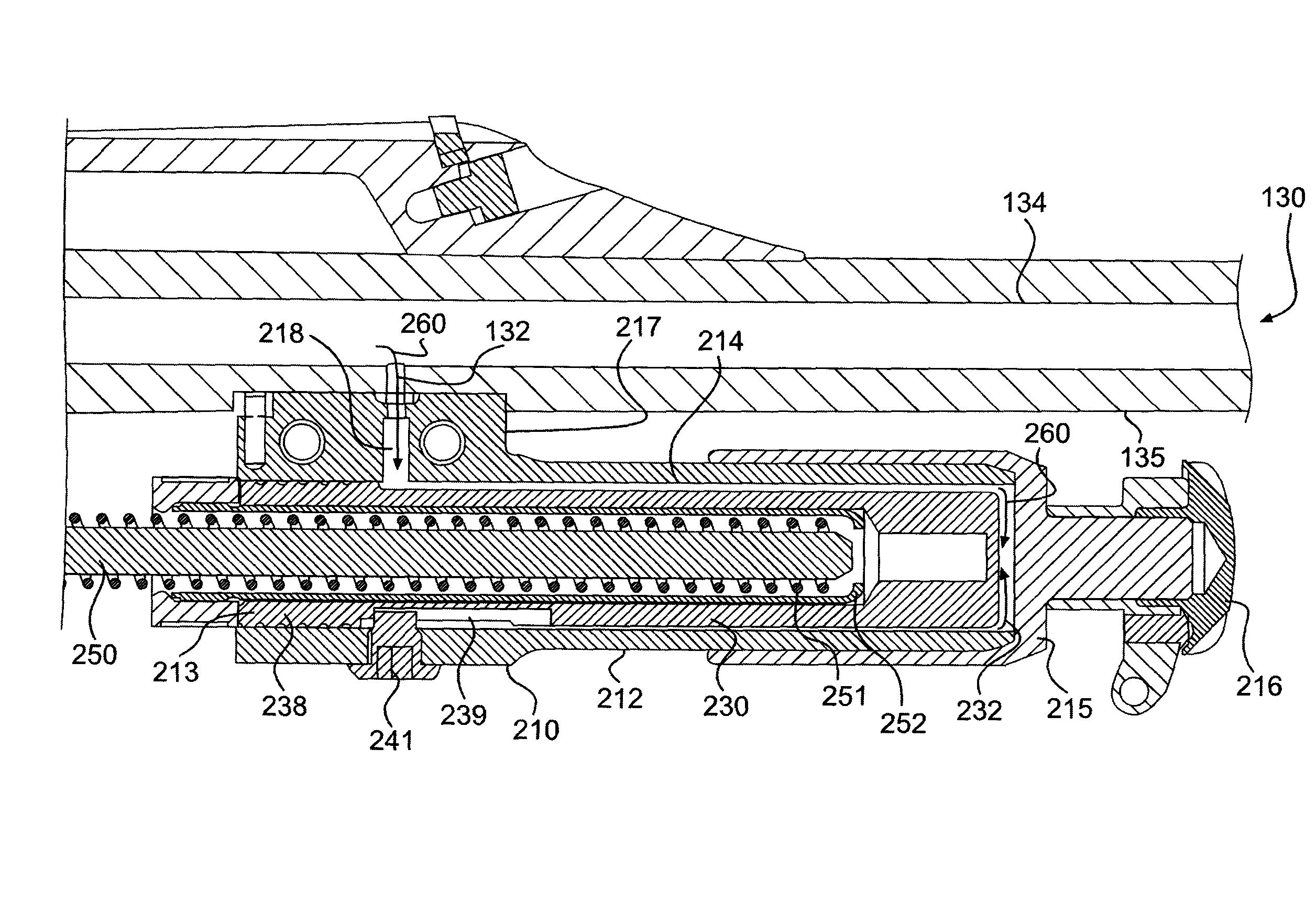
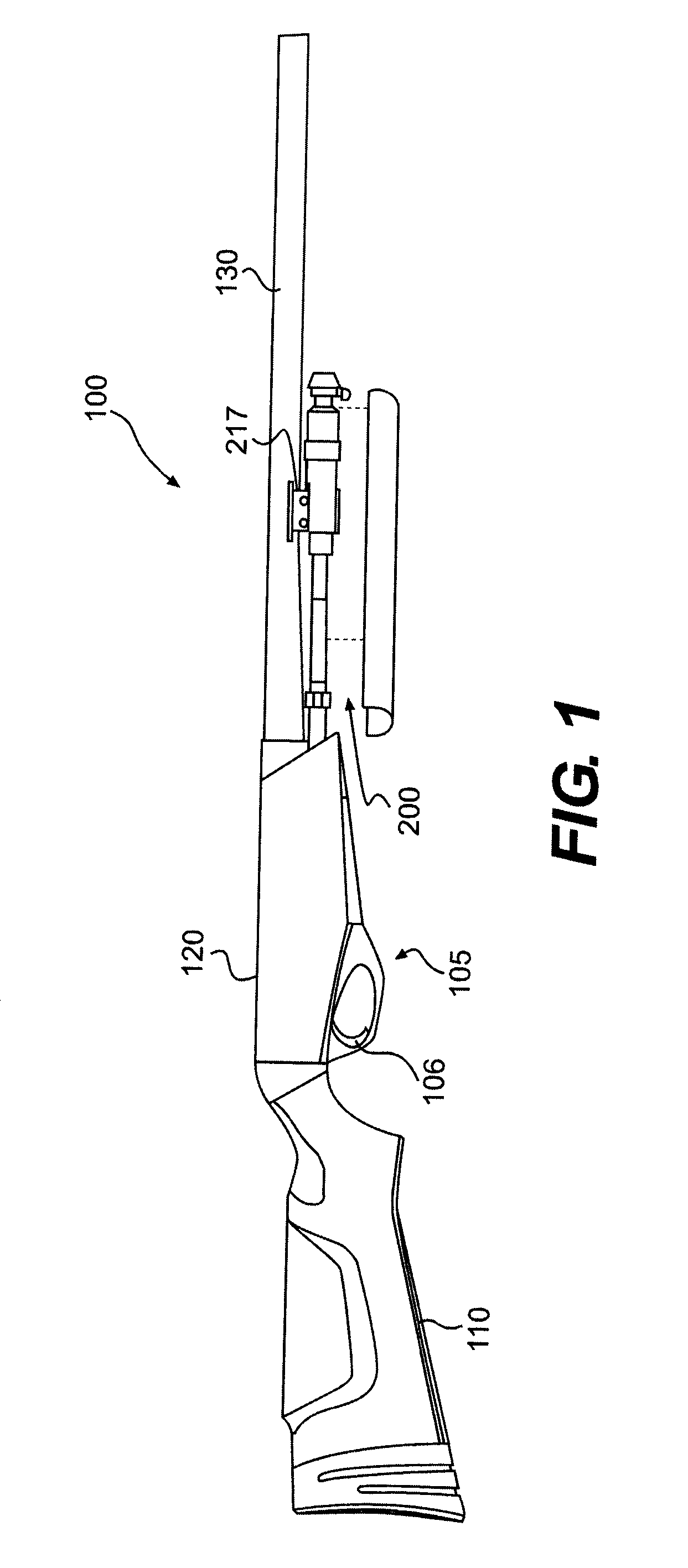
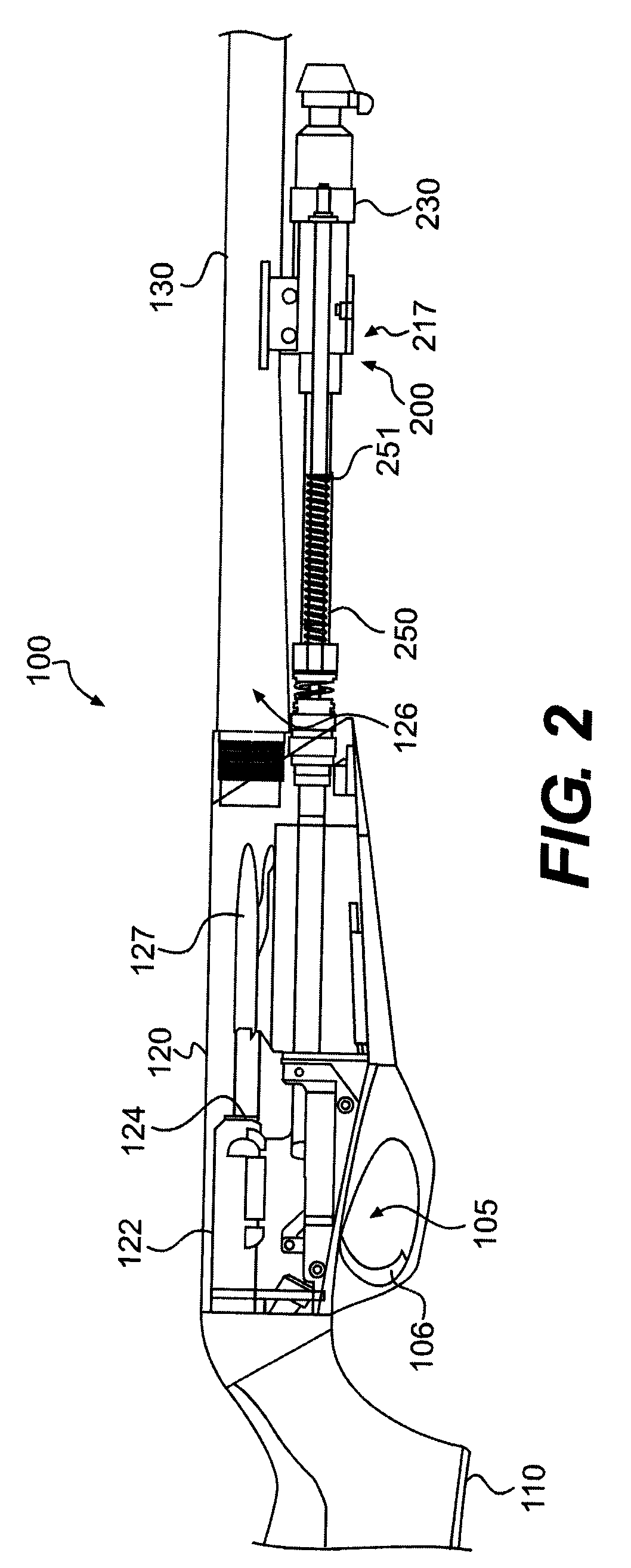
[0022]Referring now to the drawings in which like numerals indicated like parts throughout the several views, FIGS. 1 and 2 illustrate one example embodiment of the gas redirecting piston assembly according to the principles of the present invention for use in a firearm such as a rifle, although it will be understood that the gas redirecting piston assembly can be used in various types of firearms including shotguns and other long guns, hand guns and other gas operated firearms. Those skilled in the relevant art further will recognize that many changes can be made to the embodiments described, while still obtaining the beneficial results of the present invention. It will also be apparent that some of the desired benefits of the present invention can be obtained by selecting some of the features of the present invention without utilizing other features. Accordingly, those who work in the art will recognize that many modifications and adaptations to the present invention are possible ...


PUM


Abstract

A piston assembly is provided for a gas-operated firearm of the type having a chamber and a barrel. The piston assembly includes a gas expansion housing and a piston mounted within the gas expansion housing. An annular recess is formed in the outer wall of the piston to receive exhaust gases diverted from the barrel upon firing of the firearm. At least one longitudinally extending groove extends from the annual recess to the head of the piston and forms a pathway for diverting the exhaust gases to the head of the piston. During firing, pressurized gases are diverted into the annular recess and expand longitudinally from the annular recess to the piston head, whereupon the pressurized exhaust gas drives the gas piston rearwardly along the housing.

Description

CROSS REFERENCE TO RELATED APPLICATIONS[0001]This application claims the benefit of U.S. Provisional Application No. 60 / 968,733, entitled GAS SYSTEM FOR FIREARMS, filed Aug. 29, 2007, which application is incorporated herein by reference in its entirety.FIELD OF THE INVENTION[0002]The present invention generally relates to an assembly for directing expanding propellant gases from the chamber of a firearm to an expansion chamber housing a piston for semi-automatic firearms.BACKGROUND OF THE INVENTION[0003]Semi-automatic firearms, such as rifles and shotguns, are designed to fire a round of ammunition, such as a cartridge or shotshell, in response to each squeeze of the trigger of the firearm, and thereafter automatically load the next shell or cartridge from the firearm magazine into the chamber of the firearm. During firing, the primer of the round of ammunition ignites the propellant (powder) inside the round, producing an expanding column of high pressure gases within the chamber ...

Claims


Application Information

Patent Timeline
Patent Type & Authority Patents(United States)
IPC IPC(8): F41A5/18
CPCF41A5/18F41A5/28F41A5/26
Inventor STONE, JEFFREY W.
Owner REM TML HLDG LLC
Why Eureka
Try Eureka