
Dual mode combustion operation of a pulse detonation combustor in a hybrid engine

a hybrid engine and pulse detonation technology, applied in the direction of machines/engines, intermittent jet plants, lighting and heating apparatus, etc., can solve the problems of added complexity, cost and weight of aircraft engines, and the difficulty of operating pulse detonation combustor in all flight conditions, and achieve the effect of efficient operation and highly efficient combustion stag

Inactive Publication Date: 2011-05-31
GENERAL ELECTRIC CO
View PDF6 Cites 30 Cited by
  • Summary
  • Abstract
  • Description
  • Claims
  • Application Information

AI Technical Summary

Benefits of technology

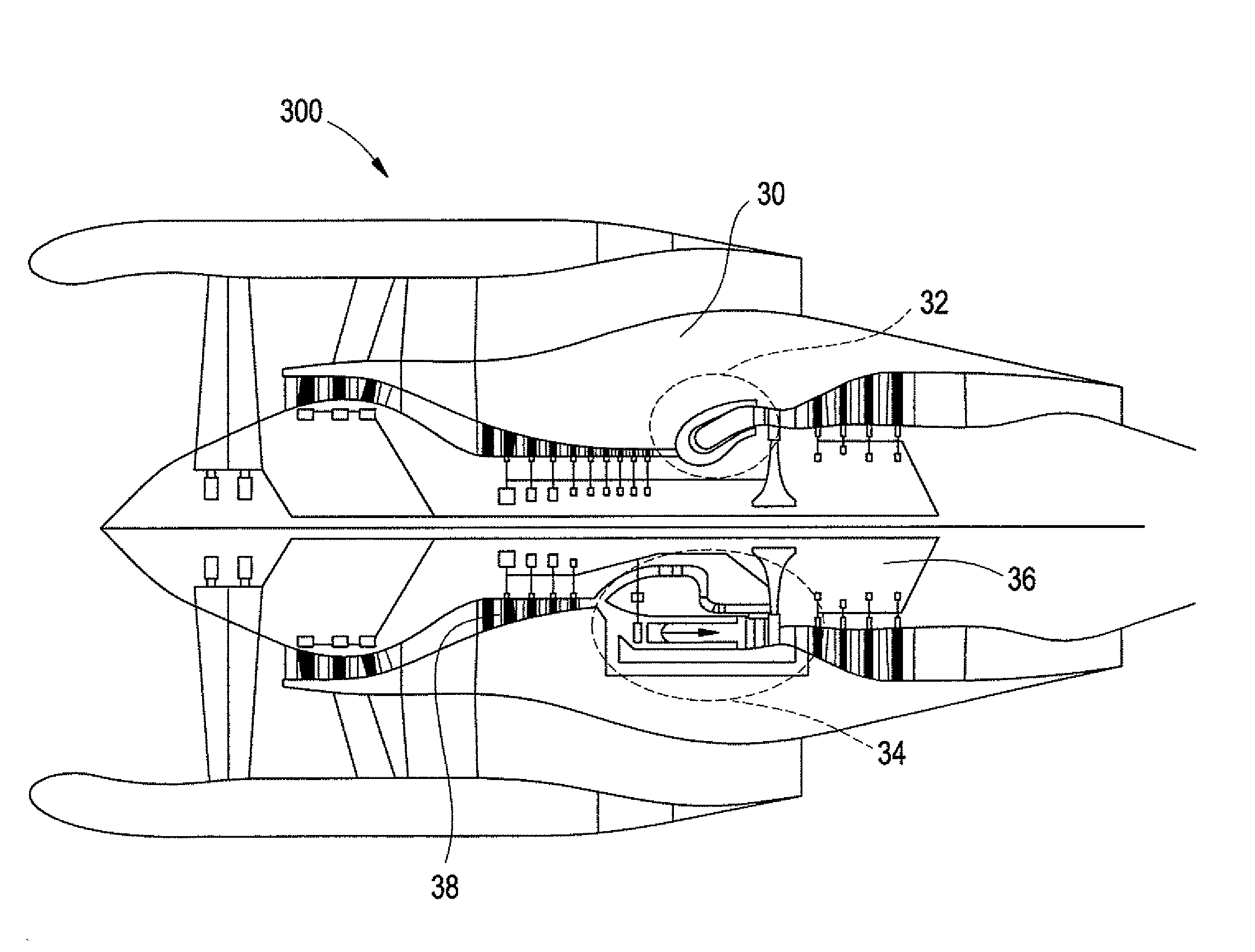
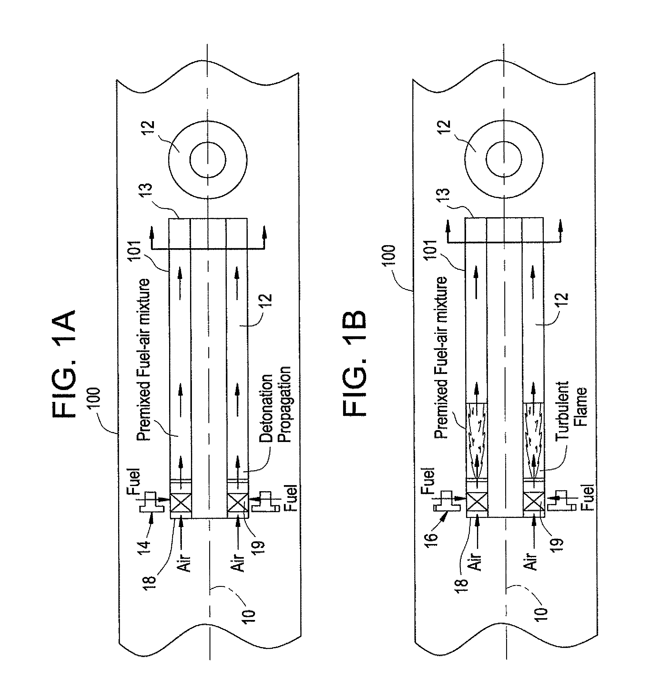
[0005]In an embodiment of the invention, a gas turbine engine contains a dual-mode combustor which can be operated in a steady, constant pressure combustion, or deflagration, mode and a pulse detonation mode. This allows the dual mode combustor to operate efficiently in all flight conditions. Specifically, in the present invention the dual mode combustor will operate in a steady, constant pressure deflagration mode during certain portions of the flight envelope and as a pulse detonation combustor in other portions of the flight envelope. This ensures that the dual mode combustor is able to operate in all possible flight conditions, providing a highly efficient combustion stage.
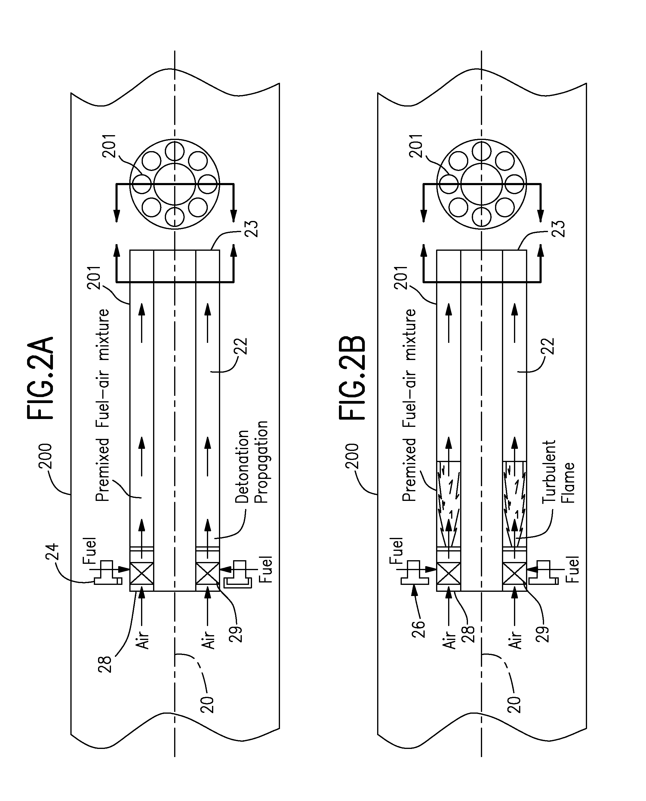
[0009]In an alternative exemplary embodiment, a similar structure is used as in the above second exemplary embodiment except that during certain engine operation parameters a number of the combustors are operated in pulse detonation mode while the others are operation in a steady, constant pressure deflagration mode. This produces a mixture of steady constant pressure deflagration and unsteady pulse detonation from the dual mode combustor, thus optimizing performance in those flight conditions where such a combustor output is optimal. However, this embodiment also allows all of the combustors to operate in steady, constant pressure deflagration mode or pulse detonation mode as the flight conditions require.

Problems solved by technology

Because of the wide variety of inlet conditions experienced during flight, it is difficult to operate a pulse detonation combustor throughout all flight conditions, which are functions of Mach number and altitude.
However, this results in added complexity, cost and weight to an aircraft engine for a benefit which can be obtained only during limited portions of the flight envelope.

Method used


Image

  • Dual mode combustion operation of a pulse detonation combustor in a hybrid engine
  • Dual mode combustion operation of a pulse detonation combustor in a hybrid engine
  • Dual mode combustion operation of a pulse detonation combustor in a hybrid engine

Examples


Embodiment Construction

[0016]The present invention will be explained in further detail by making reference to the accompanying drawings, which do not limit the scope of the invention in any way.

[0017]FIGS. 1A and 1B show a diagrammatical representation of a cross-sectional side view of a gas turbine engine 100 incorporating a first exemplary embodiment of the present invention (along with the end view). As depicted, in this embodiment the engine 100 contains a dual mode combustor section 101, having a combustion chamber 12 formed in an annulus shape. As shown, the combustion chamber 12 has a cross-sectional shape in an annulus form, which extends along a length of the dual mode combustor 101, and is centered about an engine axis. Although an annulus cross-section is depicted in these figures, it is noted that the present invention is not limited to this cross-sectional shape and additional cross-sections are contemplated. For example, it is contemplated that a hexagonal cross-section may be used, as well ...


PUM


Abstract

A dual mode combustor of a gas turbine engine contains at least one dual mode combustor device having a combustion chamber, a fuel air mixing element, a high frequency solenoid valve and a fuel injector. During a first mode of operation the dual mode combustor device operates in a steady, constant pressure deflagration mode, receiving its fuel from the fuel injector. In a second mode of operation the dual mode combustor device operates in a pulse detonation mode, receiving its fuel from the high frequency solenoid valve.

Description

BACKGROUND OF THE INVENTION[0001]This invention relates to pulse detonation systems, and more particularly, to dual mode pulse detonation systems which are capable of operating in both detonation and deflagration modes.[0002]With the recent development of pulse detonation combustors (PDCs) and engines (PDEs), various efforts have been underway to use PDCs in practical applications, such as combustors for aircraft engines. In typical aircraft engines, the combustor stage is a steady, constant pressure combustor which provides a steady, constant pressure, such as that provided by deflagration.[0003]During normal operation, a conventional gas turbine engine experiences a wide variety of engine inlet conditions to the combustor. When used on aircraft these inlet conditions are experienced throughout the different phases of flight. For example, the combustor will experience different inlet conditions during takeoff, top of climb, cruise and landing. Because of the wide variety of inlet c...

Claims


Application Information

Patent Timeline
Patent Type & Authority Patents(United States)
IPC IPC(8): F02K5/02
CPCF02K3/06F23R7/00F23R3/286F02K7/06
Inventor TANGIRALA, VENKAT ESWARLURASHEED, ADAMDEAN, ANTHONY JOHN
Owner GENERAL ELECTRIC CO
Learn More