
High velocity mass accelerator and method of use thereof

a technology of mass accelerator and accelerator, which is applied in the direction of solid balls, sport apparatus, and cumulative acceleration that leads to hypervelocities, can solve the problems of increasing the complexity of the mechanical mass accelerator track geometry, and increasing the gyration speed, so as to achieve the effect of increasing the structural stability of the track and adding rigidity to the track

Inactive Publication Date: 2011-05-31
ADVANCED LAUNCH TECH +1
View PDF23 Cites 15 Cited by
  • Summary
  • Abstract
  • Description
  • Claims
  • Application Information

AI Technical Summary

Benefits of technology

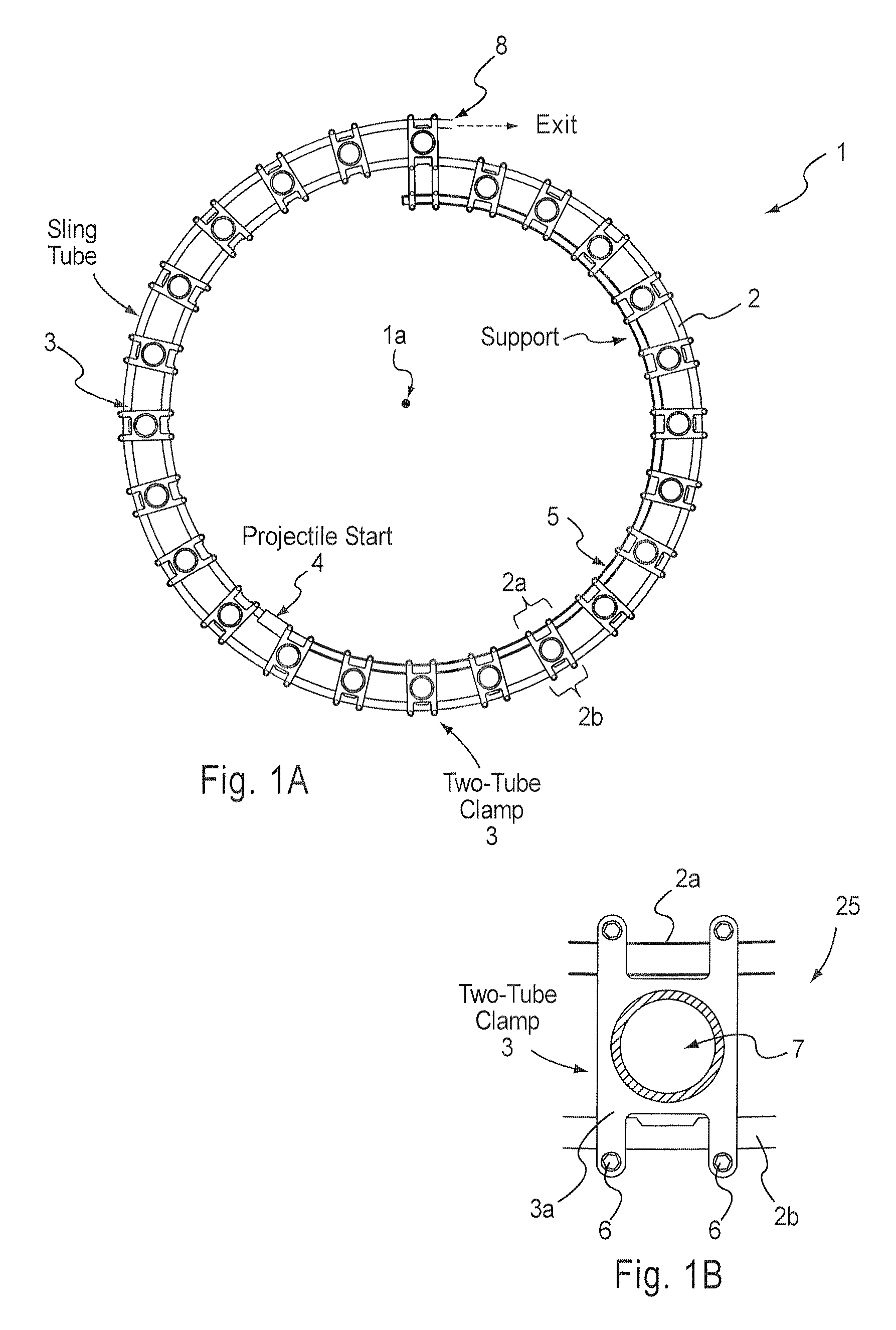
[0013]The track may further include at least one vent for venting gases produced in acceleration of a mass. This vent may comprise an opening in the track on a side opposite the side that comes in contact with the mass. The vent may be provided proximate to the clamping member, in order to provide greater structural stability of the track.
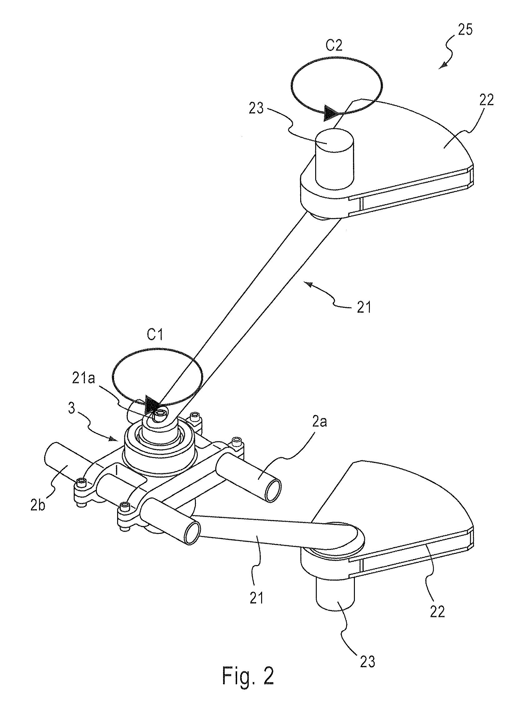
[0014]The clamping member may add rigidity to the track by receiving two sections of the track. The arm assembly may be provided at oblique angles to each other, or parallel to each other. The counterweights may be displaced from the location of the arm assembly.
[0016]Aspects of the present invention may further include a housing configured to receive at least a portion of the apparatus, and wherein the housing includes a pressure feature for one of reducing the pressure within the housing and filling the housing with a selected gas.

Problems solved by technology

Repeating this process many times and doing so in phase, creates a cumulative acceleration that leads to hypervelocities.
The acceleration is similar to rolling a ball bearing around in a circular frying pan in a horizontal plane (or sliding an ice cube around in an ice-cold pan) and gyrating the pan around in a small circle, except that mechanical mass accelerator gyration speeds are orders of magnitude greater and the mechanical mass accelerator track geometry can be more complicated than the circular track created by the edge of the pan.
While earlier mass launchers were serviceable, they were often too inefficient to be useful, required complicated parts that were not easily machined or replaced, lacked efficient means for projectile storage as well as projectile release, and included aspects with a lower structural stability and exhibited a relatively high degree of frictional dissipation.

Method used


Image

  • High velocity mass accelerator and method of use thereof
  • High velocity mass accelerator and method of use thereof
  • High velocity mass accelerator and method of use thereof

Examples


Embodiment Construction

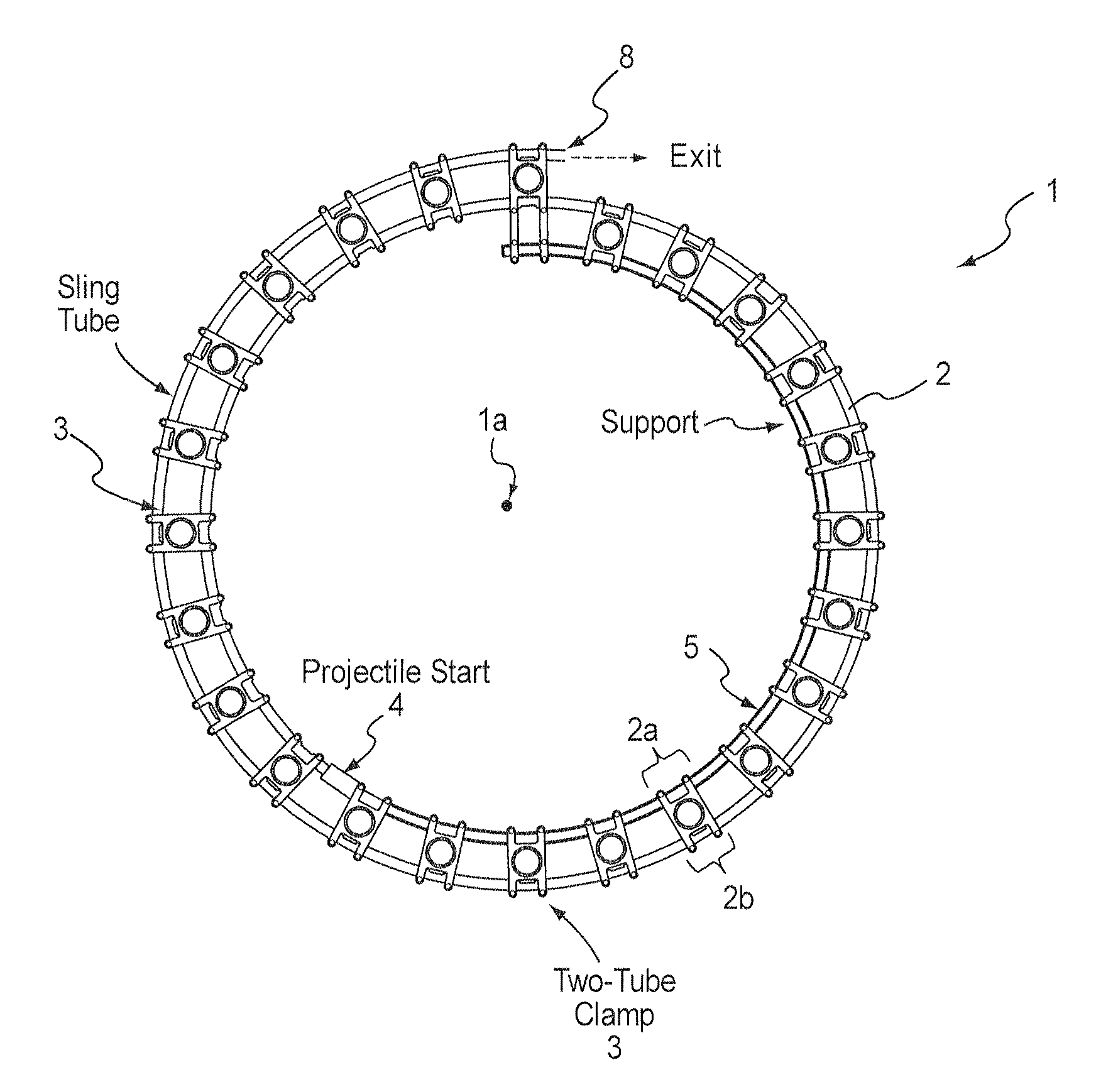
[0050]Aspects of the present invention will now be described in connection with FIGS. 1-23. These figures are meant to show variations of components that may be incorporated in many different designs of a mechanical mass accelerator as well as other devices incorporating a mechanical mass accelerator. Although the geometry of the arcuate path is illustrated in the Figures as a simple example approximating a few turns, such as ring turns, spiral turns, and helical turns, it is evident that more complicated geometries, e.g. involving a larger number of ring or spiral turns, could be assembled from the same basic components. It is to be understood that FIGS. 1-23 are not meant to be an exhaustive record of the designs and configurations for mechanical mass accelerators. Rather, these figures show some of the basic components and illustrate some of the basic concepts that may be used to construct any number of mechanical mass accelerator-based devices. The term “basic components” is not...


PUM


Abstract

An apparatus for moving a mass, the apparatus having an arcuate track, a clamping member attached to a section of the arcuate track, an arm assembly pivotably connected to the clamping member, and a counterweight connected to the arm assembly. A projectile for use in a mass accelerator having an arcuate track, the projectile having a core and at least one of a low-friction layer, a propellant layer, and a polycarbonate layer.

Description

[0001]This application is based upon and claims the benefit of priority from the prior U.S. Provisional Application No. 60 / 935,138 filed on Jul. 27, 2007, titled A MECHANICAL HYPERVELOCITY MASS ACCELERATOR, the entire contents of which are incorporated herein by reference.[0002]Additional details of the dynamics of these machines can be found in a book entitled “Slingatron—A Mechanical Hypervelocity Mass Accelerator”, D. A. Tidman, published by Aardvark Global Publishing LLC, 2007, the contents of which are incorporated herein by reference.BACKGROUND OF THE INVENTION[0003]1. Field of the Invention[0004]The present invention relates to devices, systems, and methods for accelerating a mass along a spiral or arcuate gyrating path that accelerates and launches the mass.[0005]2. Background of the Related Art[0006]The following patents listing the present inventor discuss mass accelerators, the entire contents of each of which are incorporated herein by reference: U.S. Pat. No. 5,699,779,...

Claims


Application Information

Patent Timeline
Patent Type & Authority Patents(United States)
IPC IPC(8): F41B3/04
CPCF41B3/04Y10T74/18552Y10T74/18544
Inventor TIDMAN, DEREK A.
Owner ADVANCED LAUNCH TECH
Learn More