
Wholly wrapped railroad crosstie and its manufacturing method

a crosstie and manufacturing method technology, applied in the field of railroad crosstie, can solve the problems of shortening the service life of the crosstie, deteriorating and aging, and being susceptible to damage, and achieve the effect of shortening the service li

Inactive Publication Date: 2011-05-31
6732667 MANITOBA
View PDF12 Cites 25 Cited by
  • Summary
  • Abstract
  • Description
  • Claims
  • Application Information

AI Technical Summary

Benefits of technology

"The present invention introduces a new type of wholly wrapped railroad crosstie and its manufacturing method. The new crosstie solves the problems of current composite railroad crossties such as abrasion, lower reliability, short service life, and accident cracks. The inner core is made of a supporting framework and inserts, and the outer casing is made of recycled materials like rubber and plastic. The new crosstie has the following technical effects: the outer casing completely covers the inner core, avoiding separation and friction problems and increasing reliability and service life; the production procedure is simplified and the assembly of the outer casing is no longer needed, reducing labor cost; and the materials of the outer casing are all recycled, contributing to protection of the environment and forests as well as preserving timber."

Problems solved by technology

However, a wooden crosstie is susceptible to damages caused by exposure to sunlight, wind and rain.
Thus, it easily deteriorates and ages, which shortens its service life.
This increases the cost of replacement and maintenance.
Because forest resources are becoming scarce, it is necessary to search for alternative material instead of wood to make crossties.
However, conventional concrete crossties are too hard to use conventional and standard fastening systems (tie plates and spikes).
Furthermore, each crosstie must be individually loaded and obstructed from the mold.
However, what appeared to have been a significantly lower maintenance cost due to the lack of “pumping” of the ballast rock, has actually become another maintenance cost.
The concrete crosstie is so hard that it pulverizes the ballast rock beneath it, which brings adversely effects the train operation.
More importantly, the concrete crossties provide a stiff and hard driving system without good shock absorption function, which limits the speeding up of trains.
Although crossties made out of composite materials provide significantly longer life than conventional wooden crossties, it has not been possible to provide composite crossties that are durable enough to withstand the heavy repeated loads of main line railroad tracks.
Both wooden and composite railroad crossties tend to pump ballast rock away from the rails, thus requiring frequent reballasting.
It can not only reduce environmental impact but also protect forest.
On the other hand, rigidity of the concrete crosstie and the ballast rocks are so high that the ballast rocks get crushed by constant friction and vibration, which reduces the safety factor of railroad.
This results in further cost.
However, the technical solution of the Chinese Patent No. 99815337.0 also has very clear disadvantages.
The wooden screws are very easy to be destroyed and the glue on the interfaces of the two parts is easy to be broken so that the top and the lower parts may mismatch or separate.
Therefore, it increases the probability of destruction.
Because there is certain space between the outer casing and the inner casing when the crosstie is subject to lateral force, such space exacerbates the abrasion and separation of the crosstie as a result of greatly reducing in reliability and service life and even causing the cracks and damage to the outer casing of the crosstie.
In addition, the manufacture techniques of the above composite crosstie have drawbacks.
The production and assembly of the outer casing are separately done in two production lines, which results in extra investment on the equipment, more complicated procedure, more labor as well as a lower production rate.

Method used


Image

  • Wholly wrapped railroad crosstie and its manufacturing method
  • Wholly wrapped railroad crosstie and its manufacturing method
  • Wholly wrapped railroad crosstie and its manufacturing method

Examples


Embodiment Construction

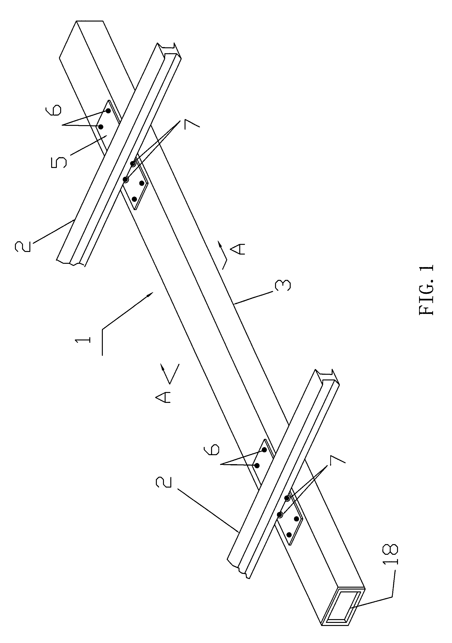
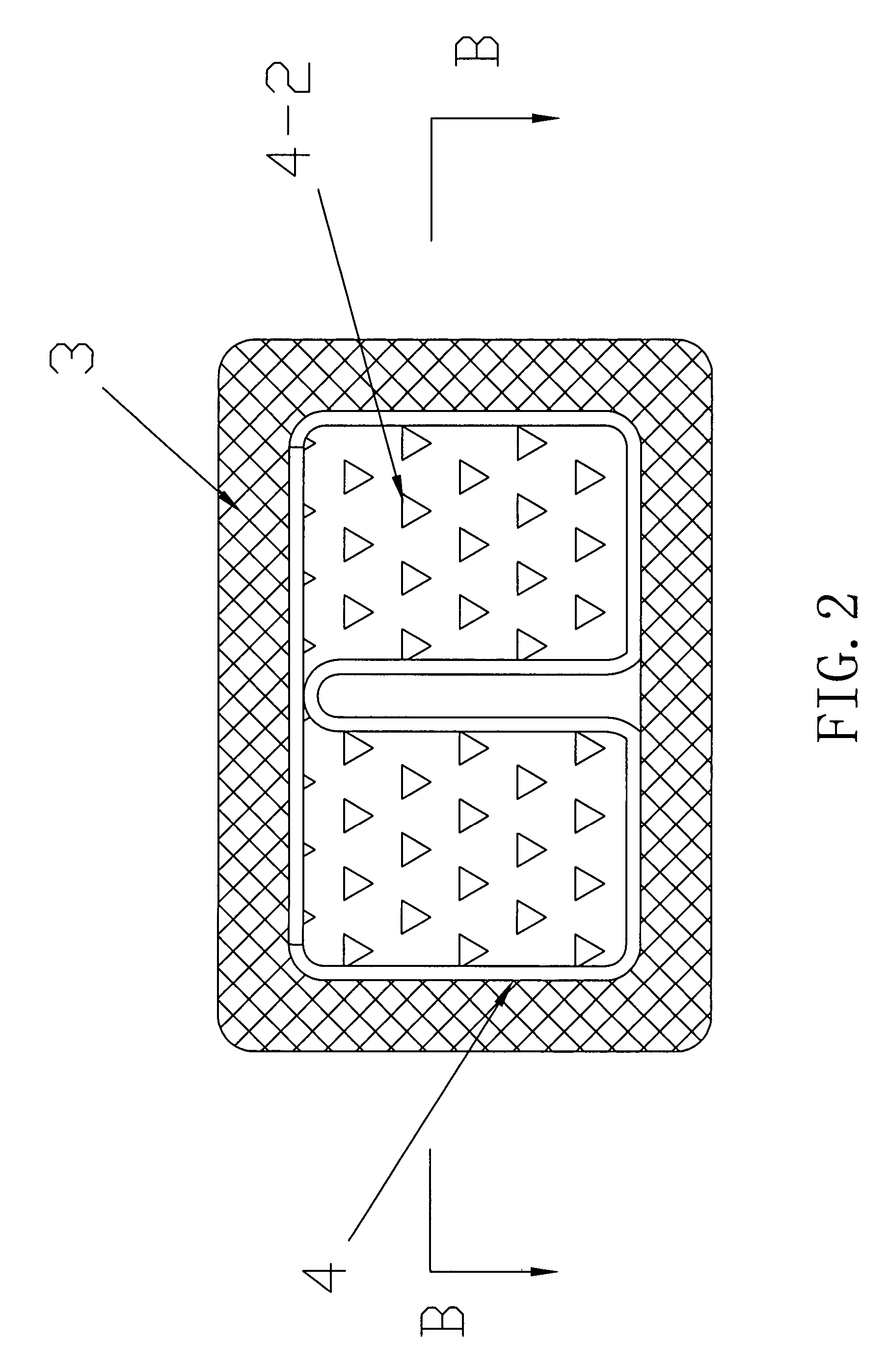
[0048]As showed in FIG. 1, reference numeral 1 represents the railroad crosstie made according to the principle of the present invention. It supports substantially parallel rails by means that is generally known to a skilled artisan. The crosstie 1 includes the outer casing 3 that is formed in a way to completely cover the inner core 4. During the manufacturing process, the outer casing material 3 melts and covers on the inner core 4 as a single integrated object. Therefore, there is not any space between the outer casing 3 and the inner core 4. In this very example, the thickness of the outer casing is 25.4 mm but it can also be changed according to different requirements.

[0049]The supporting areas for the rails 2 are set up on the crosstie plate 5 of the outer casing 3. The crosstie plates 5 are firmly secured to the crosstie 1 by fasteners 6. The conventional spikes 7 are driven through the apertures of the crosstie plates 5 into the crosstie 1 securing the rails 2 to the crossti...


PUM

PropertyMeasurementUnit
thicknessaaaaaaaaaa
shapeaaaaaaaaaa
volumeaaaaaaaaaa

Abstract

A wholly wrapped railroad crosstie comprises an inner core and an outer casing that is made of deformable composite materials. The outer casing is molten and integrally united with and attached to the inner core as a whole when it is formed. The outer casing completely covers the inner core. There's no seam on the crosstie at all. So it successfully avoids the separation and friction of the crosstie. It greatly increases the reliability and service life of the crosstie, and reduces the cost of maintenance.

Description

CROSS-REFERENCE TO RELATED APPLICATION(S)[0001]The present invention is a continuation-in-part application of the International Application No. PCT / CN2006 / 001685 filed Jul. 14, 2006 and published in Chinese, which claims the benefit of Chinese Application No. 200510044128.9 filed Jul. 21, 2005.FIELD OF THE INVENTION[0002]The present invention relates to a railroad crosstie and a method of making the same.BACKGROUND OF THE INVENTION[0003]Railroad crossties have been made almost exclusively of wood from the beginning of the railroad age. The wooden crossties are held in place by ballast rocks and the rails are secured to the crossties by crosstie plates and spikes.[0004]Because of the nature of timber, the wooden crossties accept and hold spikes, so that the rail and crosstie plate fastening systems can be secured to the crossties. This is the main advantage of the wooden crossties. In addition, a wood crosstie will flex under load. The resulting flexing is beneficial only in that it ...

Claims


Application Information

Patent Timeline
Patent Type & Authority Patents(United States)
IPC IPC(8): E01B21/00B29C48/06B29C48/151E01B3/46
CPCB29C47/0016B29C47/021E01B3/46B29K2021/00B29K2023/12B29K2025/00B29K2105/0044B29K2023/06B29C48/06B29C48/151
Inventor YUAN, QIANG
Owner 6732667 MANITOBA
Learn More