Emulsified polymer drilling fluid and methods of preparation

a drilling fluid and polymer technology, applied in the field of drilling fluids, can solve the problems of increasing viscosity, reducing viscosity, oil thick and heavy, and difficult recovery, and achieve the effect of enhancing the ability of drilling fluid to emulsify bitumen

Inactive Publication Date: 2011-05-31
SECURE ENERGY DRILLING SERVICES
View PDF28 Cites 36 Cited by
  • Summary
  • Abstract
  • Description
  • Claims
  • Application Information

AI Technical Summary

Benefits of technology

[0028]The drilling fluid may also include one or more of the following constituents: polymer materials, alkaline materials, a carrier oil having solvent properties, weighting materials, and defoaming agents. As used in this patent specification, a carrier oil having solvent properties means an oil with properties rendering it effective to enhance the drilling fluid's ability to emulsify the bitumen into the drilling fluid.

Problems solved by technology

Some polymers may decrease the viscosity of the mud, while others may act to cause flocculation of the clay in the mud, thus increasing viscosity.
Not all surfactants are emulsifiers, however.
However, a particular problem arises when drilling through oil-bearing sand formations, such as those which occur extensively in northern Alberta.
These oil sand formations contain vast reserves of oil, but the oil is thick and heavy and therefore difficult to recover.
However, the usefulness of such methods is limited to recovery from oil sand formations that are close enough to the surface of open-pit mining to be practical.
Conventional production well technology, which relies on crude oil flowing by gravity and / or pressure into production wells, does not work well or at all in bituminous oil sand formations.
Being quite thick and heavy, the oil in these formations is typically too viscous, in its natural state, to flow out of the sand.
If its viscosity is low enough to permit gravity flow, recovery rates tend to be very low.
However, drilling in bituminous oil sand formations poses a number of practical problems that are not satisfactorily addressed by prior art drilling mud technology.
The cuttings contain significant amounts of heavy oil or bitumen, which can clog the shale shaker screens and other mud-processing equipment.
As a result, effective removal of cuttings from the mud is more difficult, and the ability to clean and reuse the mud is reduced or even precluded.
This increases mud costs, because new mud must be added to the mud system to replace mod that cannot be effectively cleaned and must therefore be discarded.
This gives rise to the further problem of disposal of the discarded mud, laden with substantial quantities of sand coated with heavy oil and bitumen.
Disposal of this contaminated mud is considerably more difficult, from both practical and environment standpoints, then disposing of the comparatively clean particulate material removed from the mud in more conventional drilling operations.
Furthermore, the cuttings are very sticky because of the thick oil and bitumen, and they tend to stick to the drilling pipe, well casing, and liners.
The presence of these sticky cuttings in the mud increases drag forces on the drill string components, thereby increasing the power and torque required to rotate the drill string, increasing wear and tear on the rig's drive mechanism, and increasing rig service and maintenance requirements.
The sticky cuttings and bitumen cause particular problems when running liners into a horizontal well, because they tend to build up in curved casing sections where the well changes direction from vertical to horizontal, often making it necessary to clear the build-up before it will be possible to run the liners into the horizontal section without difficulty.
The major drawback to this solution is expense, as the cost of operating a mud cooler can commonly be several thousand dollars per day.
However, this formulation did not prove effective.
In such low concentrations, the HME ENERGIZER® could not emulsify oil and bitumen from the cuttings, and in higher concentrations it would make the mud too thick to be used in the field.
It is therefore readily apparent that while the Van Slyke compositions might be effective in certain applications, the Van Slyke patent does not address the problems caused by bitumen-laden cuttings in the specific context of water-based drilling fluids.

Method used


Image

  • Emulsified polymer drilling fluid and methods of preparation
  • Emulsified polymer drilling fluid and methods of preparation

Examples


Embodiment Construction

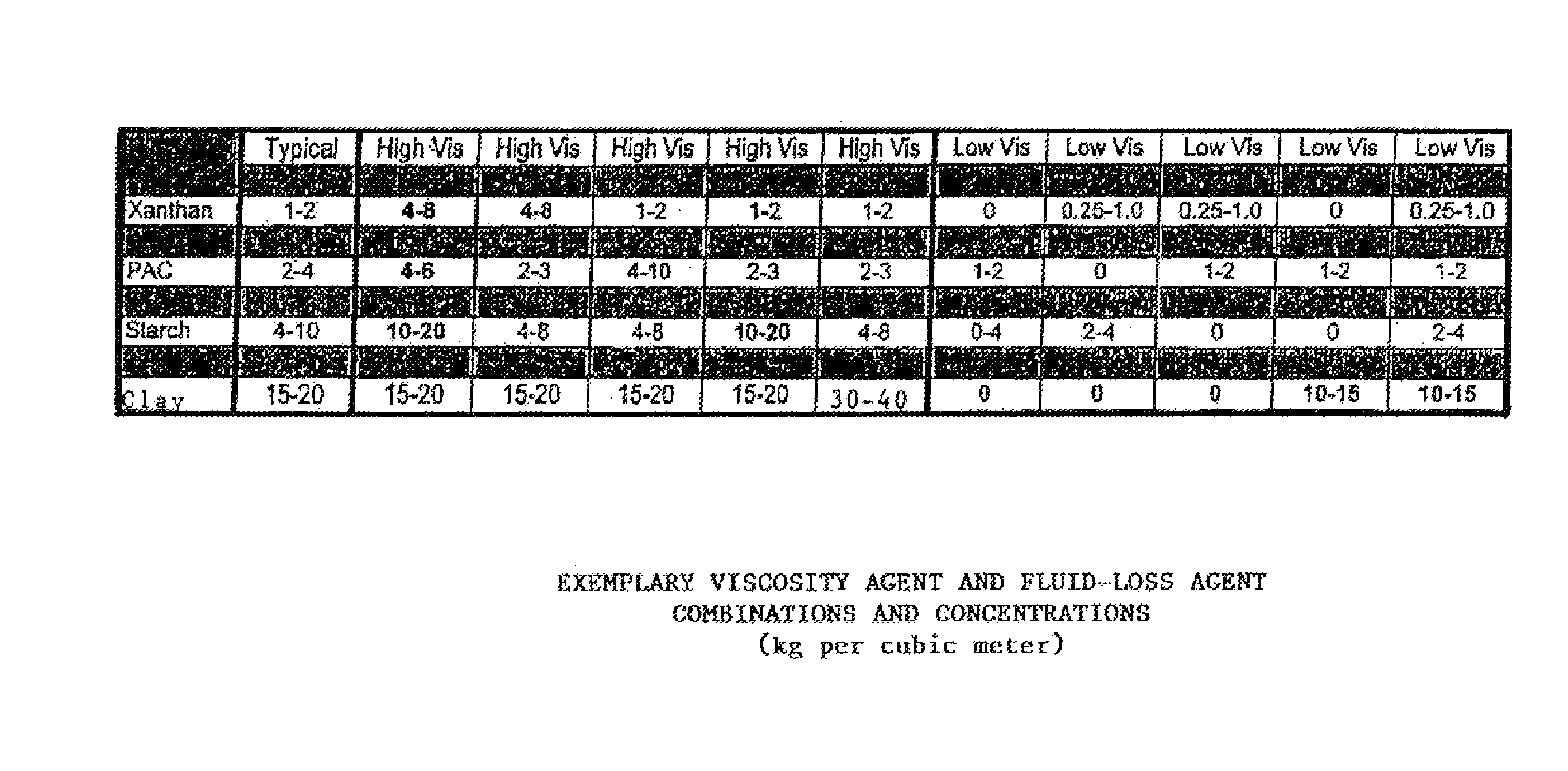
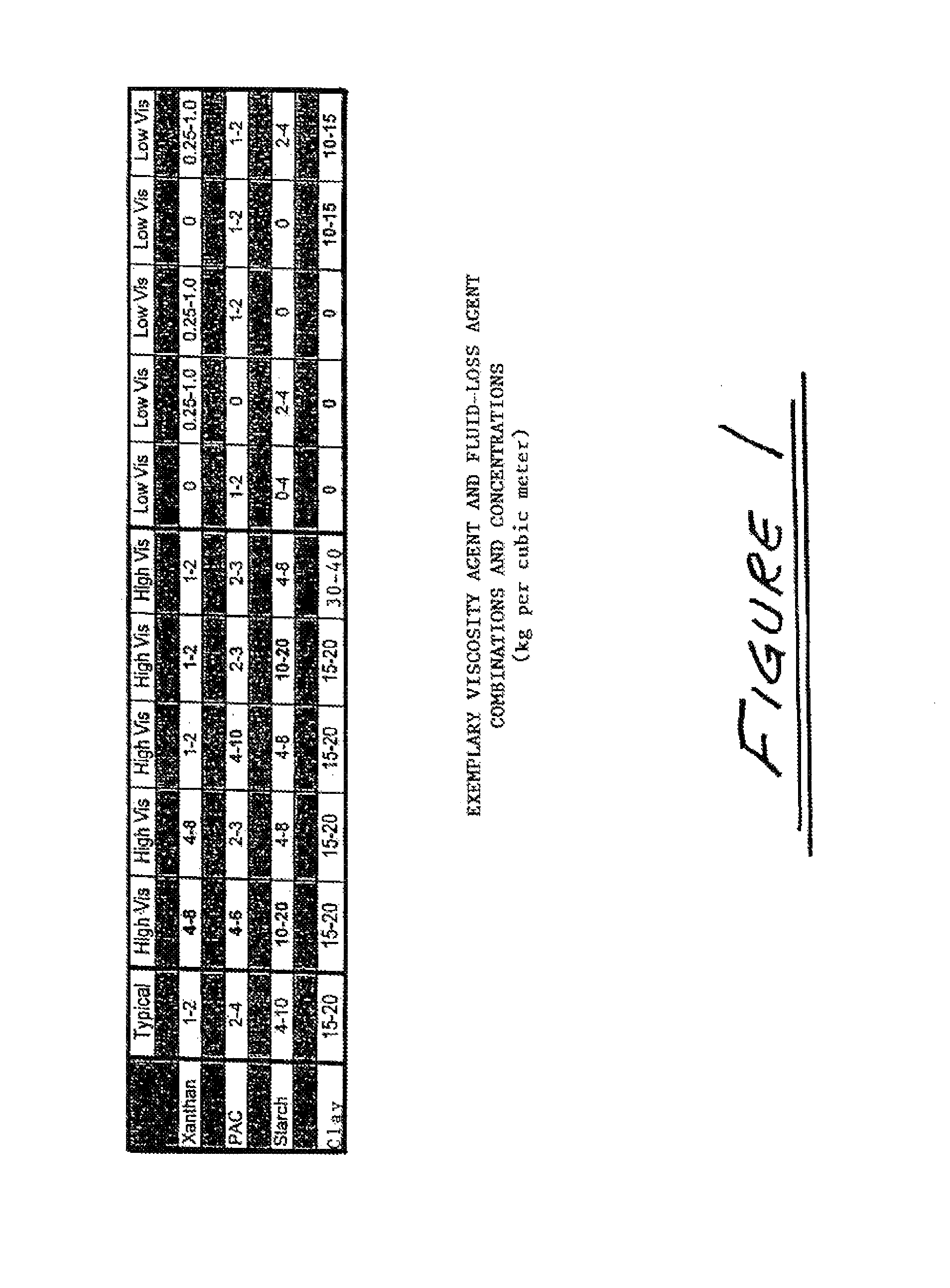
[0037]The essential and optional constituents of the drilling fluids of the present invention have been set out above. The invention does not require these constituents to be combined in specific relative proportions or set formations. The proportions of each constituent, as well as the selection of optional constituents, will be variable depending on the particular characteristics of the subsurface materials through which a well using the drilling fluid is being drilled, and also depending on particular drilling fluid characteristics that the user may wish to obtain. However, typical ranges for the concentrations of the various constituents are set out below, along with examples of specific materials that may be used for the constituents.

[0038]In preferred embodiments of the drilling fluid of the invention, the viscosity agent may be PAC (polyanionic cellulose), clay, starch, or xanthan gum. Where a clay is used as a viscosity agent, it will be a clay of a type adapted for or known...


PUM

PropertyMeasurementUnit
concentrationaaaaaaaaaa

Abstract

A water-based polymer drilling fluid, containing effective quantities of surfactants having HLB numbers equal to or greater than approximately 7, emulsifies oil and bitumen contained in oil sand cuttings, resulting in the oil and bitumen being dispersed into the mud as an emulsion. This eliminates or significantly reduces the ability of the oil, bitumen, and cuttings to clog the well or stick to drill string components when drilling a well through oil-bearing sands, particularly sands containing highly viscous oil or bitumen. The emulsification process separates the sand particles from the oil and bitumen, such that the sand particles can be removed when the mud is run through a conventional shale shaker or other suitable apparatus.

Description

CROSS-REFERENCE TO RELATED APPLICATIONS [0001]This application claims the benefit, pursuant to 35 U.S.C. 120, of U.S. Non-Provisional application Ser. No. 10 / 722,529, filed on Nov. 28, 2003, which claimed the benefit, pursuant to 35 U.S.C. 119(e), of U.S. Provisional Application No. 60 / 430,051, filed on Dec. 2, 2002, and the specifications of said provisional and non-provisional applications are incorporated herein by reference in their entireties.FIELD OF THE INVENTION[0002]The present invention relates to drilling fluids for use in drilling oil and gas wells, and in particular to drilling fluids for use in drilling through oil sand formations.BACKGROUND OF THE INVENTIONDrilling Fluids Generally[0003]Oil and gas wells are most commonly drilled using the rotary drilling method. In this method, a drill bit with fixed or rotatable cutting teeth is mounted at the lower end of a drill string, which is an assembly of drill pipe, drill collars, and other drilling accessories. The drill st...

Claims


Application Information

Patent Timeline
Patent Type & Authority Patents(United States)
IPC IPC(8): C09K8/18C09K8/28
CPCC09K8/28
Inventor WU, AN-MINGBROCKHOFF, JAY
Owner SECURE ENERGY DRILLING SERVICES
Why Eureka
Try Eureka