Optical image measurement device

a measurement device and optical image technology, applied in the direction of instruments, eye diagnostics, applications, etc., can solve the problems of limiting the resolving power in the direction (horizontal direction), no efforts have been made to improve measurement, and speck noise, so as to improve measurement sensitivity and improve measurement sensitivity without narrowing a measurement range. , the effect of low temporal coheren

Active Publication Date: 2011-05-31
KK TOPCON
View PDF6 Cites 6 Cited by
  • Summary
  • Abstract
  • Description
  • Claims
  • Application Information

AI Technical Summary

Benefits of technology

[0011]The present invention has been made based on the aforementioned aspects, and an object of the present invention is to provide an optical image measurement device that enables improvement of measurement sensitivity by considering spatial coherence of light.
[0014]The optical image measurement device according to the present invention outputs a light having low temporal coherence and low spatial coherence, splits the light into a signal light and a reference light, superimposes the signal light having passed through a measured object and the reference light having passed through a reference object to generate and receive an interference light, and forms an image of the measured object based on the light receiving result. The light receiver configured to receive the interference light has a light receiving face on which a plurality of light receiving elements are arranged 2-dimensionally. The optical system of the optical image measurement device projects the interference light onto the light receiving face so that the size of the spatially coherent region of the interference light becomes equal to or larger than the size of the light receiving element on the light receiving face. According to such an optical image measurement device, it is possible to improve the measurement sensitivity.
[0015]Further, in another aspect of the present invention, the optical image measurement device outputs a light having low temporal coherence and low spatial coherence, splits the light into a signal light and a reference light, superimposes the signal light having passed through the measured object and the reference light having passed through a reference object to generate and receive an interference light, and forms an image of a measured object based on the light receiving result. The light receiver configured to receive the interference light has a light receiving face on which a plurality of light receiving elements are arranged 2-dimensionally. The optical system of the optical image measurement device projects the interference light onto the light receiving face so that the size of the spatial coherent region of the interference light becomes substantially equal to the size of the light receiving element on the light receiving face. According to such an optical image measurement device, it is possible to improve the measurement sensitivity without narrowing a measurement range.

Problems solved by technology

Moreover, the high spatial coherence causes speckle noise, and limits the resolving power in the direction (horizontal direction) orthogonal to depth direction.
However, for a conventional optical image measurement device, no efforts have been made to improve measurement with the main aim of spatial coherence.

Method used


Image

  • Optical image measurement device
  • Optical image measurement device
  • Optical image measurement device

Examples


Embodiment Construction

[0022]An embodiment of the optical image measurement device according to the present invention will be described in detail referring to the drawings.

[Configuration]

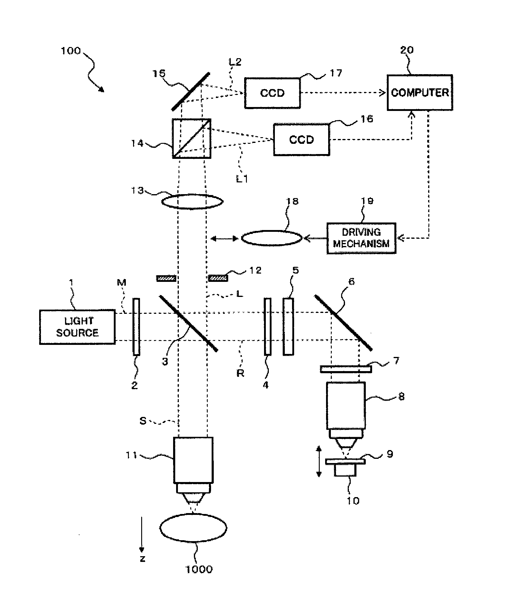
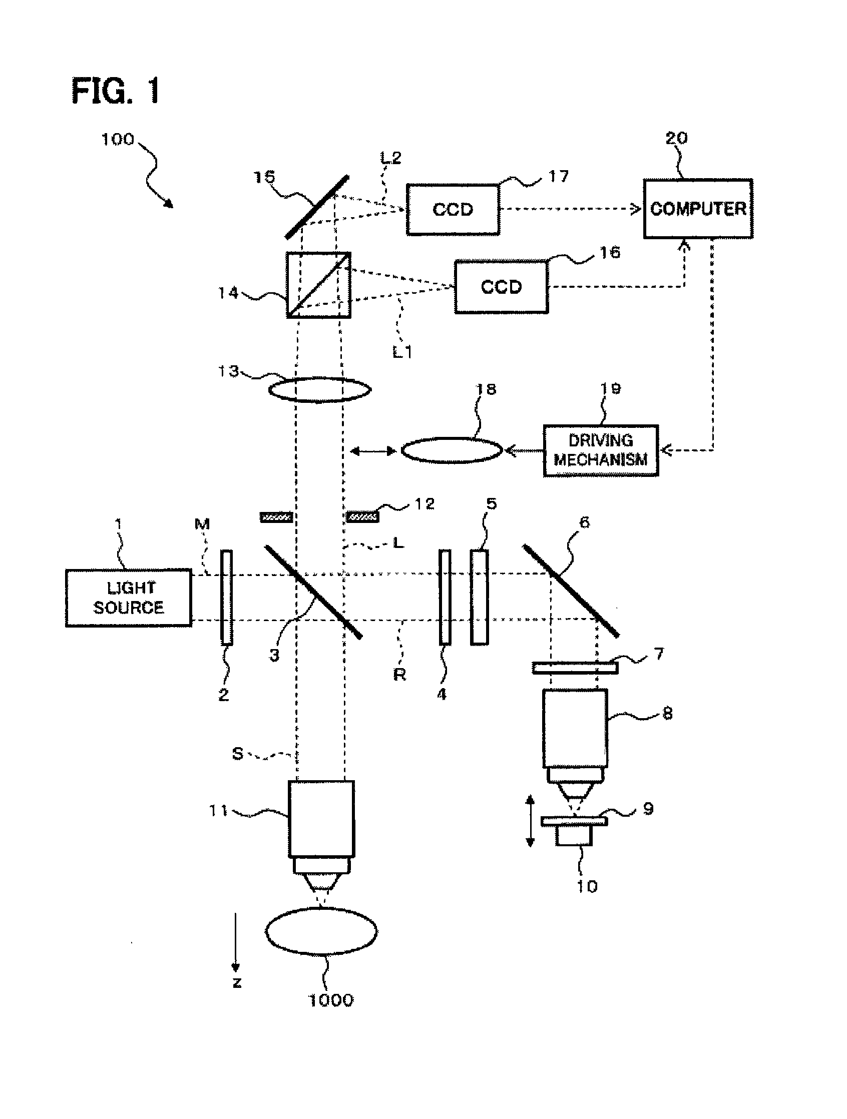
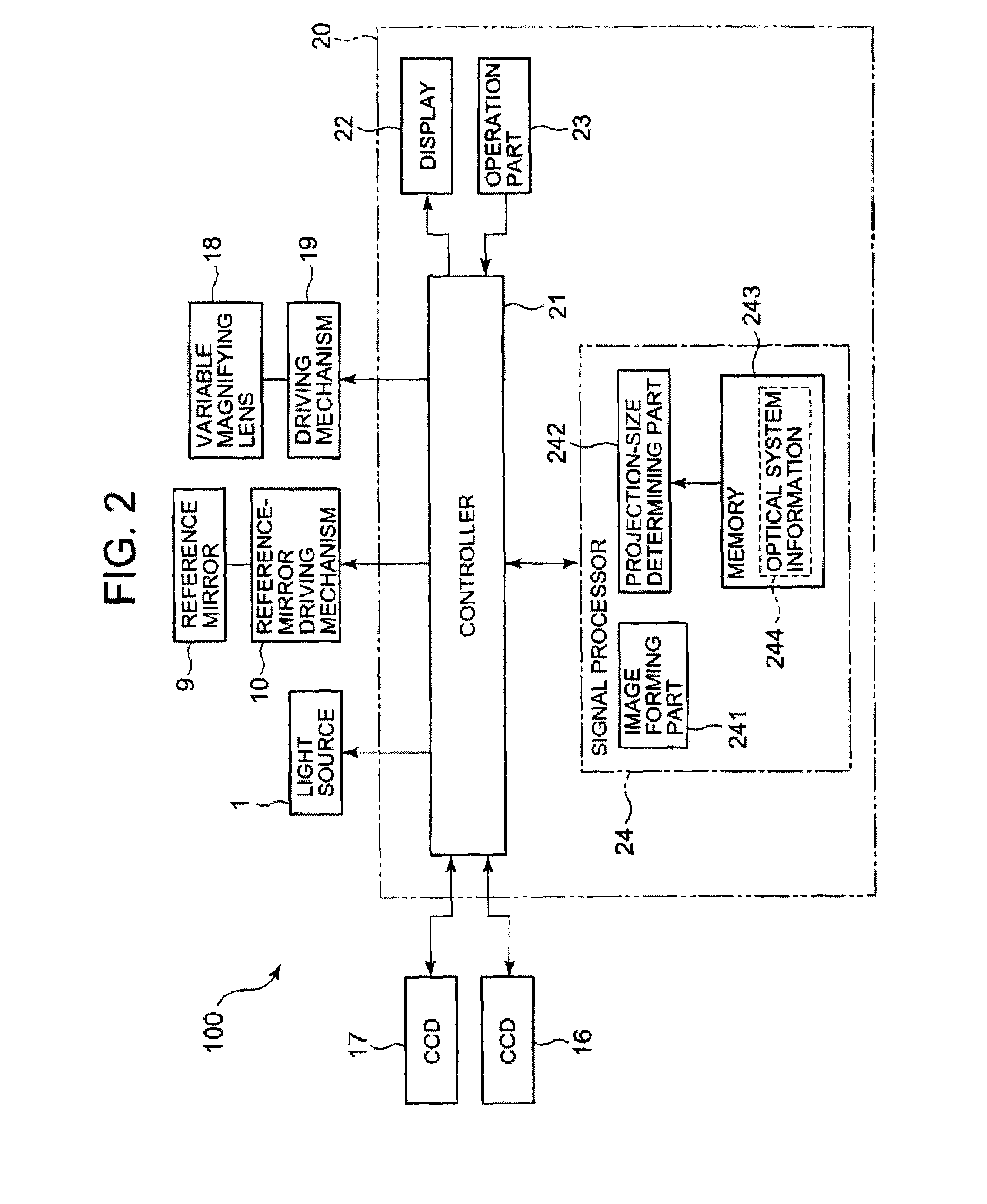
[0023]FIG. 1 shows an example of the configuration of the optical image measurement device according to the present embodiment. An optical image measurement device 100 is a full-field type OCT device. The optical image measurement device 100 applies a signal light S having a specific beam diameter onto a measured object 1000, and detects an interference light L (having a specific beam diameter) generated by superimposing the signal light S and the reference light R, with a 2-dimensional light sensor array. Furthermore, the optical image measurement device 100 analyzes the detection result of the interference light L, and thereby forms a 2-dimensional image of the region of the measured object 1000 depending on the beam diameter of the signal light S.

[0024]The measured object 1000 is placed in the condition appropriate for...


PUM


Abstract

An optical image measurement device comprises: a light source configured to output a light having low temporal coherence and low spatial coherence; an optical system configured to split the light into a signal light and a reference light and superimpose the signal light having passed through a measured object and the reference light, thereby generating an interference light; a light receiver configured to receive the interference light and output an electric signal; and a forming part configured to form an image of the measured object based on the electric signal, wherein: the light receiver has a light receiving face on which a plurality of light receiving elements are arranged 2-dimensionally; and the optical system projects the interference light onto the light receiving face so that a size of the spatial coherent region of the interference light becomes equal to or larger than a size of the light receiving element.

Description

BACKGROUND OF THE INVENTION[0001]1. Field of the Invention[0002]The present invention relates to an optical image measurement device for forming an image of a measured object by using the OCT technology.[0003]2. Description of the Related Art[0004]Recently, attention has focused on an optical image measurement device that forms an image of a measured object by using the OCT (Optical Coherence Tomography) technology. The optical image measurement device splits a low-coherence light into two (lights), and applies one (signal light) of the two to the measured object and the other (reference light) to a reference object. Then, it superimposes the signal light having passed through the measured object and the reference light having passed through the reference object to generate and detect an interference light, and analyzes the detection result to form an image of the measured object (e.g., see Japanese Unexamined Patent Application Publications JP-A 2006-153838 and JP-A 2006-116028).[0...

Claims


Application Information

Patent Timeline
Patent Type & Authority Patents(United States)
IPC IPC(8): G01B11/02G01B9/02
CPCA61B3/102G01N21/4795A61B3/112
Inventor CHAN, KINPUIAKIBA, MASAHIROFUKUMA, YASUFUMI
Owner KK TOPCON
Why Eureka
Try Eureka