Optical imaging lens assembly
a technology of optical imaging and lens assembly, which is applied in the field of optical imaging lens assembly, can solve the problems of reducing the degree of freedom in arranging the lens system, the inability to easily reduce the total track length of the system, and the complicated process of adhesion of glass lenses, so as to reduce the total track length of the lens assembly, reduce the sensitivity of the optical system, and improve the effect of image quality
- Summary
- Abstract
- Description
- Claims
- Application Information
AI Technical Summary
Benefits of technology
Problems solved by technology
Method used
Image

Examples
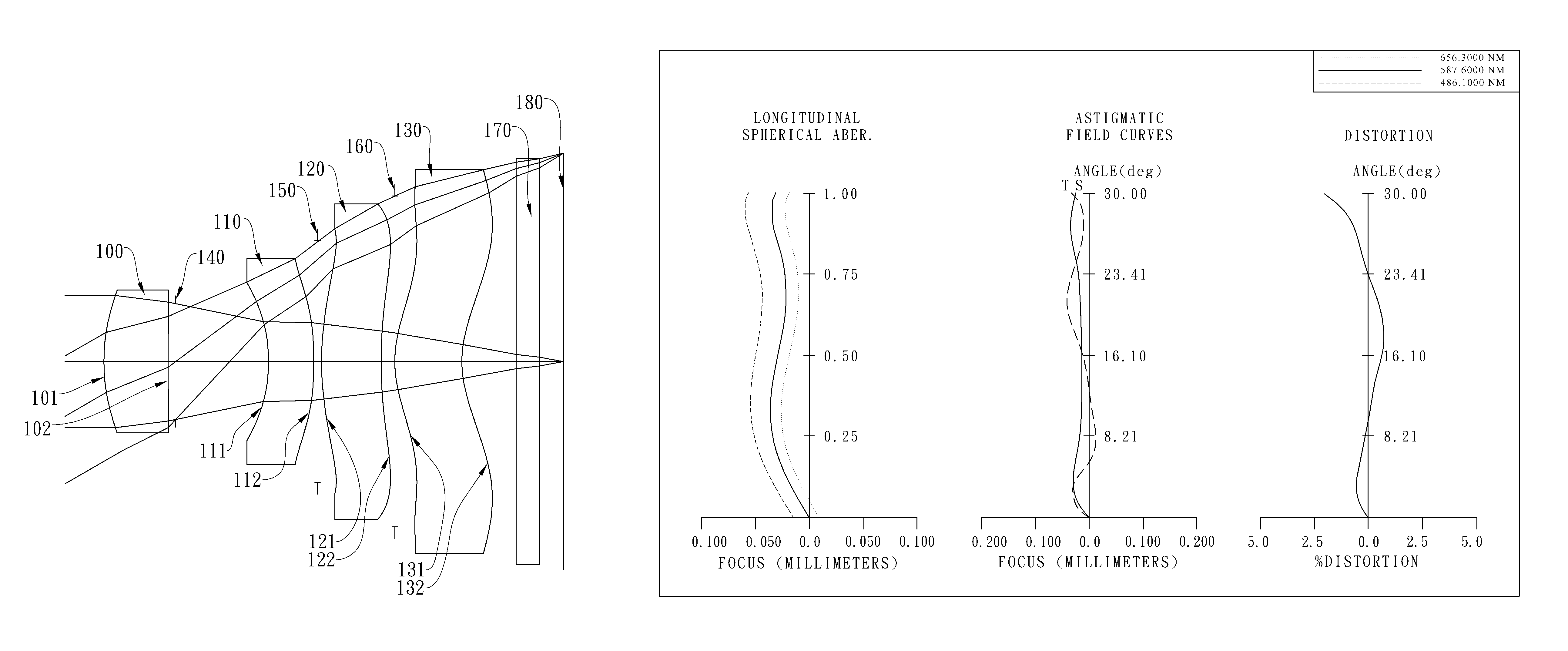
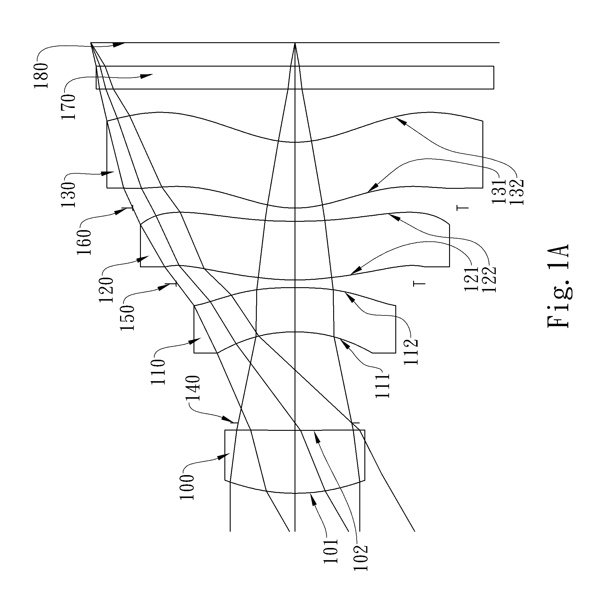
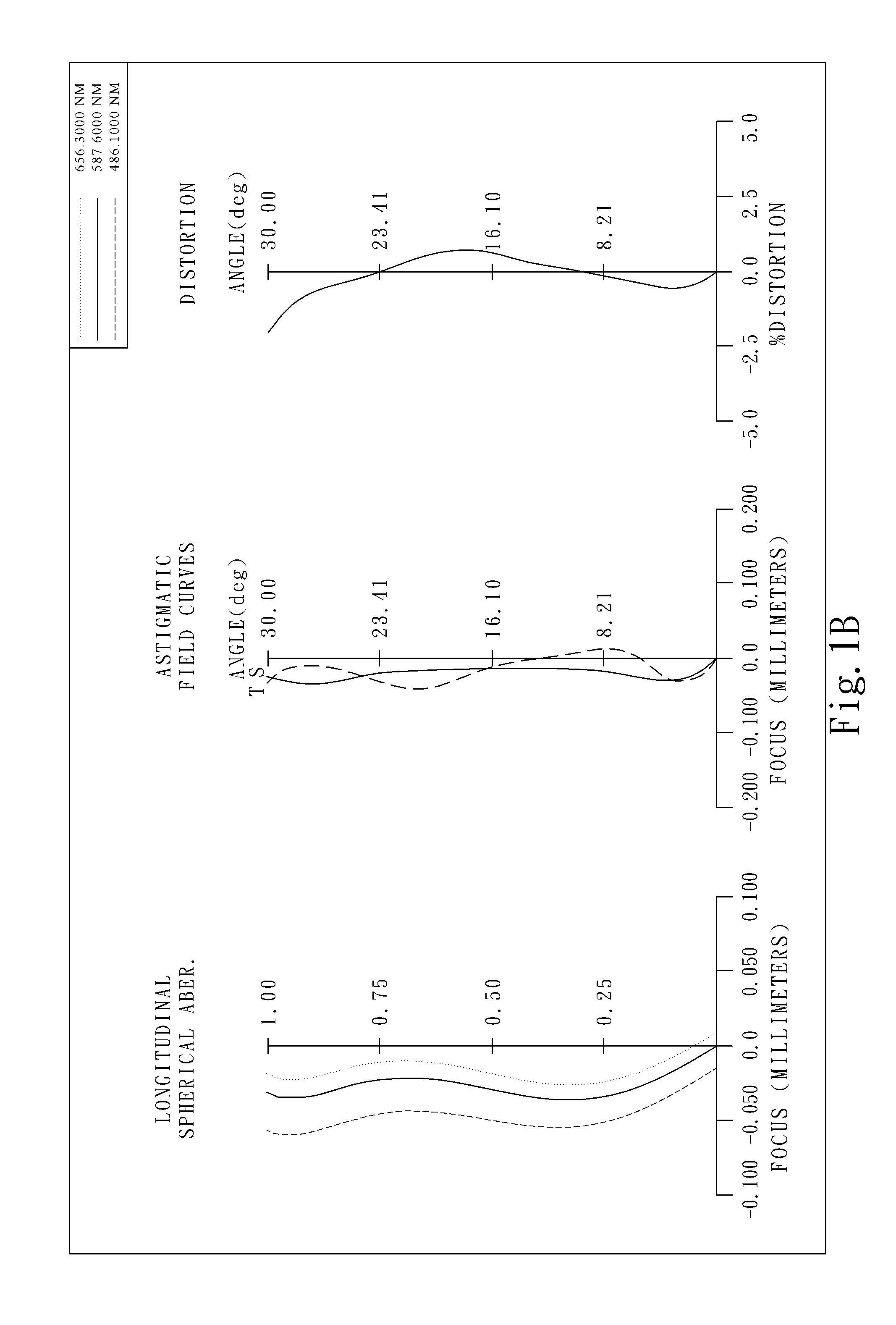
first embodiment
[0053]In the present optical imaging lens assembly, the focal length of the lens assembly is f, and it satisfies the relation: f=4.73 (mm).
[0054]In the first embodiment of the present optical imaging lens assembly, the f-number of the lens assembly is Fno, and it satisfies the relation: Fno=2.80.
[0055]In the first embodiment of the present optical imaging lens assembly, half of the maximum field of view of the lens assembly is HFOV, and it satisfies the relation: HFOV=30.0 (degrees).
[0056]In the first embodiment of the present optical imaging lens assembly, the thickness of the third lens element 120 on the optical axis is CT3, the thickness of the fourth lens element 130 on the optical axis is CT4, and they satisfy the relation: CT3 / CT4=0.89.
[0057]In the first embodiment of the present optical imaging lens assembly, the distance on the optical axis between the first lens element 100 and the second lens element 110 is T12, the focal length of the lens assembly is f, and they satisfy...
second embodiment
[0073]In the present optical imaging lens assembly, the focal length of the lens assembly is f, and it satisfies the relation: f=4.87 (mm).
[0074]In the second embodiment of the present optical imaging lens assembly, the f-number of the lens assembly is Fno, and it satisfies the relation: Fno=2.80.
[0075]In the second embodiment of the present optical imaging lens assembly, half of the maximum field of view of the lens assembly is HFOV, and it satisfies the relation: HFOV=30.0 (degrees).
[0076]In the second embodiment of the present optical imaging lens assembly, the thickness of the third lens element 220 on the optical axis is CT3, the thickness of the fourth lens element 230 on the optical axis is CT4, and they satisfy the relation: CT3 / CT4=0.72.
[0077]In the second embodiment of the present optical imaging lens assembly, the distance on the optical axis between the first lens element 200 and the second lens element 210 is T12, the focal length of the lens assembly is f, and they sat...
PUM
 Abstract
Description
Claims
Application Information
 - R&D
- Intellectual Property
- Life Sciences
- Materials
- Tech Scout
- Unparalleled Data Quality
- Higher Quality Content
- 60% Fewer Hallucinations
Browse by: Latest US Patents, China's latest patents, Technical Efficacy Thesaurus, Application Domain, Technology Topic, Popular Technical Reports.
© 2025 PatSnap. All rights reserved.Legal|Privacy policy|Modern Slavery Act Transparency Statement|Sitemap|About US| Contact US: help@patsnap.com