
Fascia cap for roof

a technology for roofs and fascia caps, which is applied in the direction of roof drainage, snow traps, building repairs, etc., can solve the problems of water entering the roof, rot and deterioration of the roof and building walls, and water penetrating the fascia cap, so as to achieve the effect of mitigating capillary action

Inactive Publication Date: 2011-06-07
C&G LOCKSYST
View PDF50 Cites 8 Cited by
  • Summary
  • Abstract
  • Description
  • Claims
  • Application Information

AI Technical Summary

Benefits of technology

[0008]Accordingly, it is an object of the present invention to provide a fascia cap design and assembly that mitigates and almost entirely eliminates capillary action. It is further object of the present invention to provide a roofing assembly with a fascia cap having a continuous elongated drip edge that works to mitigate capillary action. A further object of the invention is to have the fascia cap be in one continuous piece. A further object of the invention is to have a blocking strip as part of the assembly that reinforces the fascia cap and attaches it to the roof. It is a further object of the present invention to provide a method for a roofing assembly having a fascia cap with a continuous elongated drip edge.
[0011]In preferred embodiments, the drip edge is at least as long as the side edge. In other preferred embodiments, the drip edge is at least half as long as the side edge. In other preferred embodiments, the bottom edge is at least as long as the top edge. The assembly functions to limit water from moving through capillary action back towards the roof. The assembly mitigates surface tension allowing water to move back and up towards the roof.
[0014]Furthermore, the fascia cap may have the drip edge run the length of the bottom edge and be continuous with the bottom edge. The drip edge may limit water from moving through capillary action and surface tension back towards the roof.

Problems solved by technology

A disadvantage to prior art designs for fascia caps is that water is often able to seep between the fascia cap and the roof, causing rot and deterioration of the roof and building walls.
The surface tension results in water penetrating the fascia cap and entering the roof.

Method used


Image

  • Fascia cap for roof
  • Fascia cap for roof
  • Fascia cap for roof

Examples


Embodiment Construction

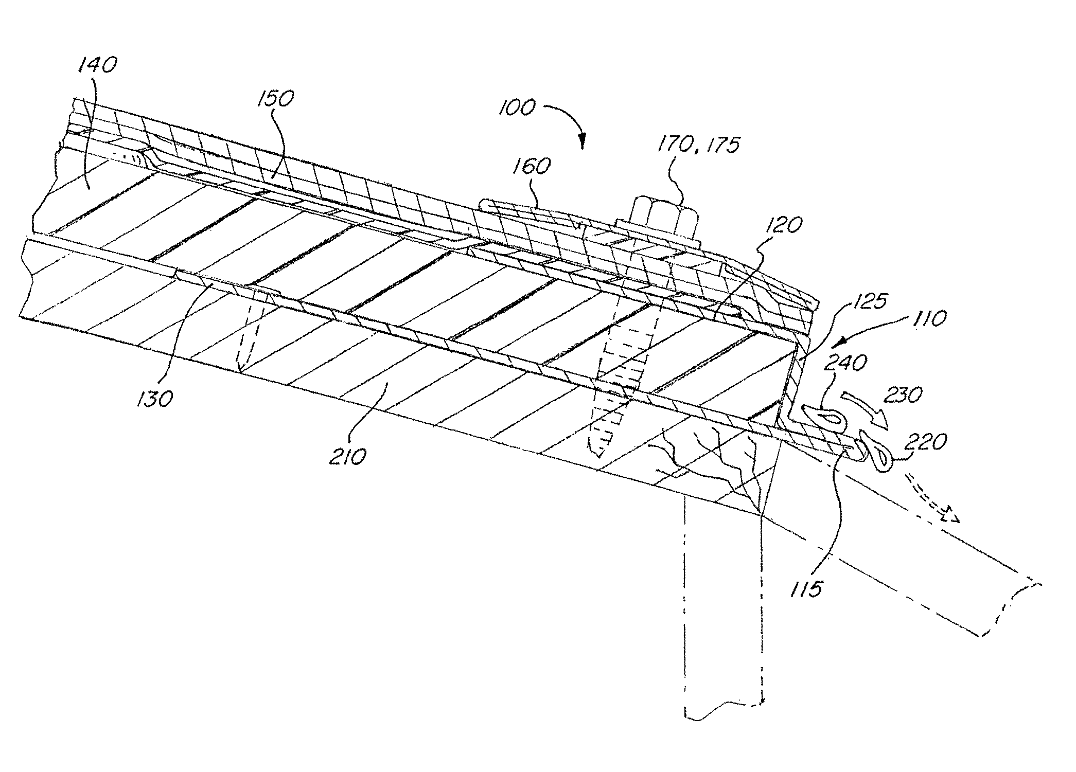
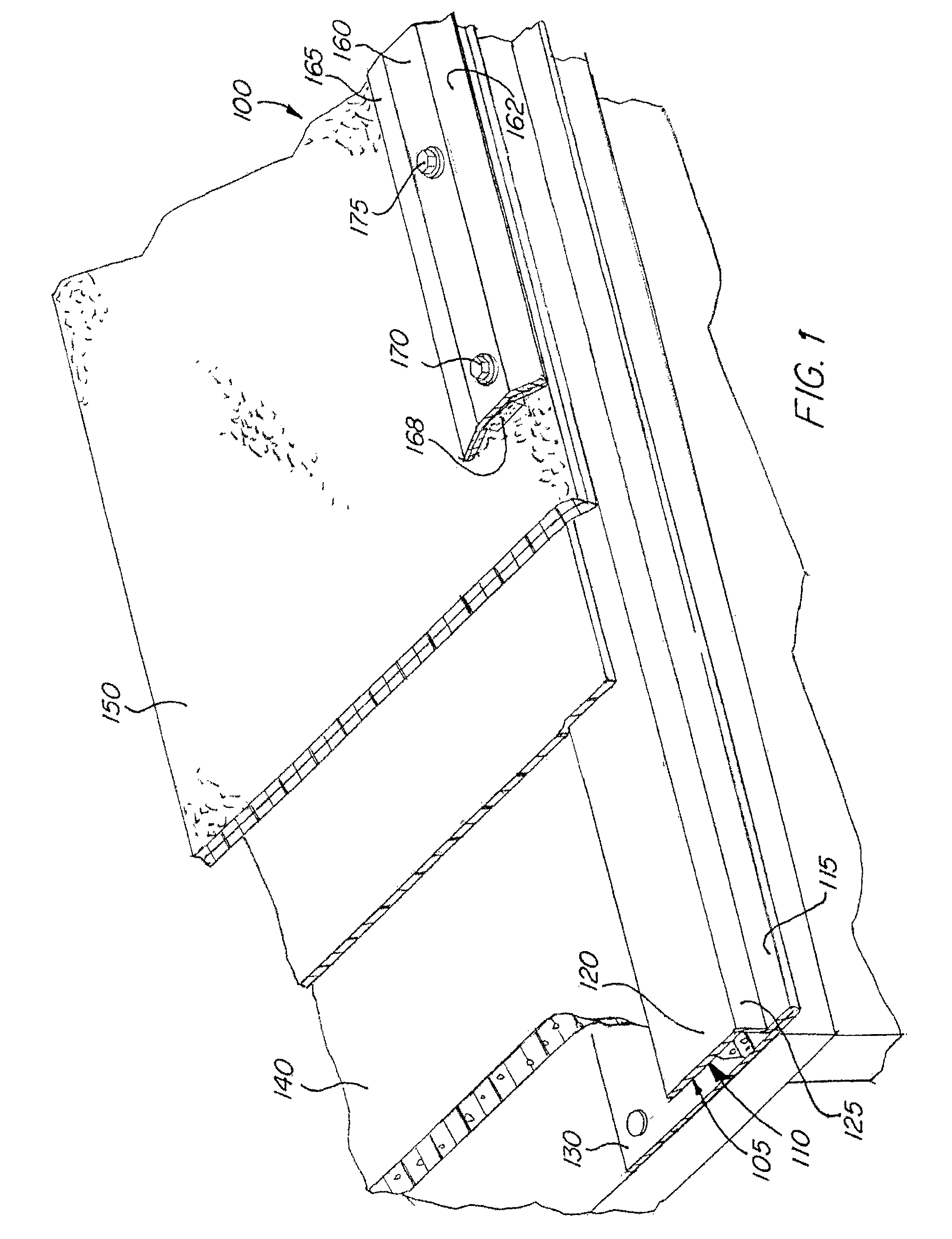
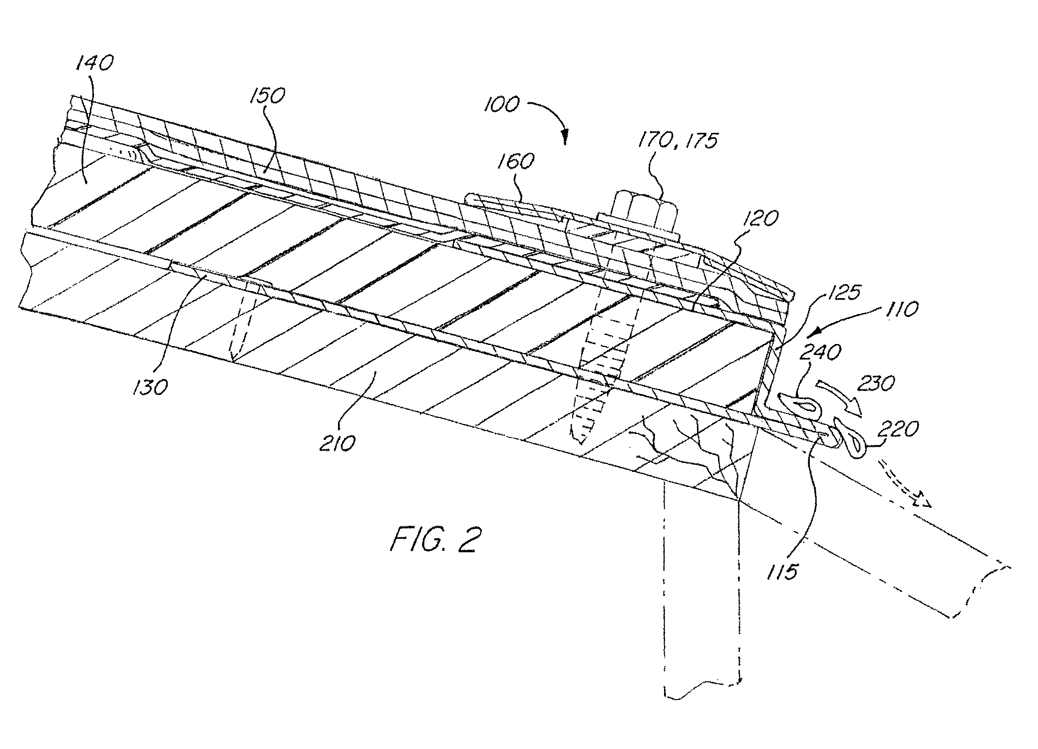
[0031]Referring to FIG. 1, an assembly 100 fitting on the end of a roof in accordance with the present invention is shown. This assembly 100 contains a fascia cap 110 having an elongated drip edge 115, top edge 120, side edge 125, and bottom edge 130. In a preferred embodiment, the fascia cap 110 is made of a single material such as a metal, metal alloy, hard plastic, or other such material used in the roofing industry. The body 105 of the fascia cap 110 is preferably a U-shape where top edge 120 and bottom edge 130 are connected by side edge 125. Bottom edge 130 has drip edge 115 extending past U-shaped body 105.

[0032]The fascia cap 110 is designed to accept a roofing material 140, such as insulation, wood, foam, or any such material that is used in the roofing and construction industry. Shingle material 150 is adapted to lay flat against the top edge of the fascia cap. Single material 150 may be standard housing shingles or other such materials designed to protect a roof from wate...


PUM


Abstract

An improved roofing method and assembly having a fascia cap designed to prevent water from moving through capillary action back towards the roof. The assembly has an a elongated drip edge running back the bottom edge of the fascia cap that displaces water away from the roof, preserving the integrity of the roof and building walls below. A blocking strip attaches the fascia cap to the roof, maintaining the assembly and helping the flow of water away from the roof.

Description

FIELD OF THE INVENTION[0001]The present invention relates to an improved fascia cap assembly for roofing. More particularly, the invention is a fascia cap assembly designed to limit water from moving through capillary action back towards the roof. The assembly has an elongated drip edge that displaces water away from the roof, preserving the integrity of the roof and building walls below. The assembly also contains a blocking strip to help the flow of water away from the roof and also to hold the assembly together.BACKGROUND OF THE INVENTION[0002]Buildings, such as houses and office buildings are made of walls and are covered by a roof. The roof is typically, but not always, downward sloping so that water can drip off the roof and away from the building.[0003]At the point where the water drips off the edge of the roof, a fascia cap is typically installed to provide protection for the roof. The edge of the roof is the place most likely to have water accumulate and a fascia cap is des...

Claims


Application Information

Patent Timeline
Patent Type & Authority Patents(United States)
IPC IPC(8): E04D13/04E04D13/158E04D13/15
CPCE04D13/15E04D13/155E04D2013/0468
Inventor COVONE, FRANCIS THOMASGOODMAN, ROBERT SHERMANBATTS, III, WILLIAM ALEXANDER
Owner C&G LOCKSYST
Learn More