Landing gear noise attenuation

a technology of landing gear and noise attenuation, which is applied in the direction of floats, functional valve types, transportation and packaging, etc., can solve the problems of creating airframe noise, various noise reduction designs, and airframe noise created by landing gear is a substantial contributor, so as to achieve the effect of reducing noise generation

Active Publication Date: 2011-06-07
THE BF GOODRICH CO
View PDF47 Cites 13 Cited by
  • Summary
  • Abstract
  • Description
  • Claims
  • Application Information

AI Technical Summary

Benefits of technology

[0019]In yet another aspect, the present invention is directed to apparati for passive noise reduction of landing gear. An exemplary apparatus is a brake cover fairing partially covering a piston and piston housing of a front brake of a landing gear assembly and having a less than full circumferential design. Another exemplary apparatus is a fairing insert suitable for inserting into a pocket of a brace belonging to a landing gear assembly, the fairing insert having a bulbous front section and a tapered rear section to help minimize noise generation. Yet another exemplary apparatus is a pocket filler fairing secured in a pocket of a brace belonging to a landing gear assembly by means of a non-removable fastener. Yet another exemplary apparatus is a door / strut interface noise reduction fairing comprising a multi-piece fairing that attaches to a shock strut via an existing hydraulic and / or electrical bracket along a length of said shock strut. Yet another exemplary apparatus is a tear-drop shaped shock strut fairing extending from an interface gap around a front of the shock and covering electrical and hydraulic lines that extend along the front of the shock, the tear-drop shaped fairing being configured to allow the shock strut to function both in a deployed pre-touchdown position, and also in compressed position after touchdown.

Problems solved by technology

The interaction of airflow with an airframe's protrusions and cavities creates airframe noise.
While engine noise dominates aircraft noise at takeoff, the airframe noise created by landing gear is a substantial contributor to approach noise for many aircraft.
While various noise reduction designs are known for fixed landing gear noise attenuators for deployable landing gears are less developed.
The complexity of non-acoustical constraints on the design of landing gears have not permitted effective and practical noise minimization designs.

Method used


Image

  • Landing gear noise attenuation
  • Landing gear noise attenuation
  • Landing gear noise attenuation

Examples


Embodiment Construction

[0057]Landing gear fairings are an effective approach to reduce noise. Fairings improve the aerodynamic characteristics of the landing gear system, such that the unsteadiness of the airflow is minimized. While fixed fairings have been used traditionally for non-retractable landing gear, the employment of fairings in conjunction with retractable landing gear is limited due to the confined space of the fuselage nose section and of the relatively thin wing sections.

[0058]Due to size constraints, a full enveloping fixed fairing for a landing gear is not feasible. Alternatively, significant noise attenuation is achievable by partially fairing critical components of landing gear.

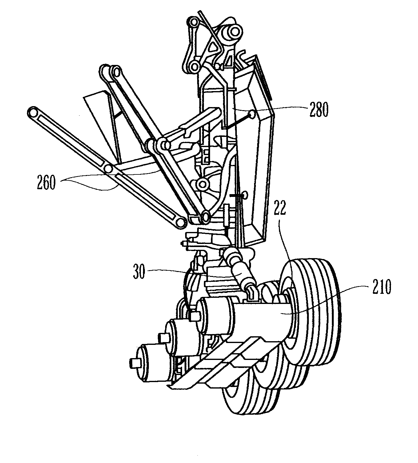
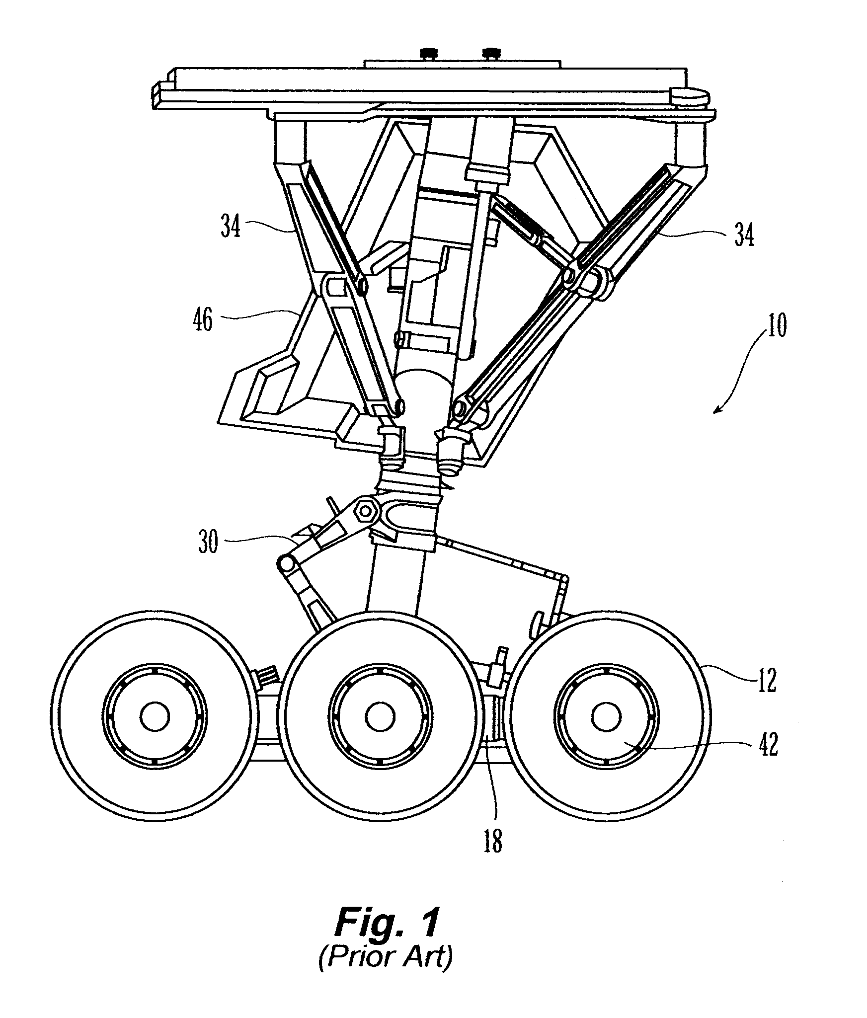
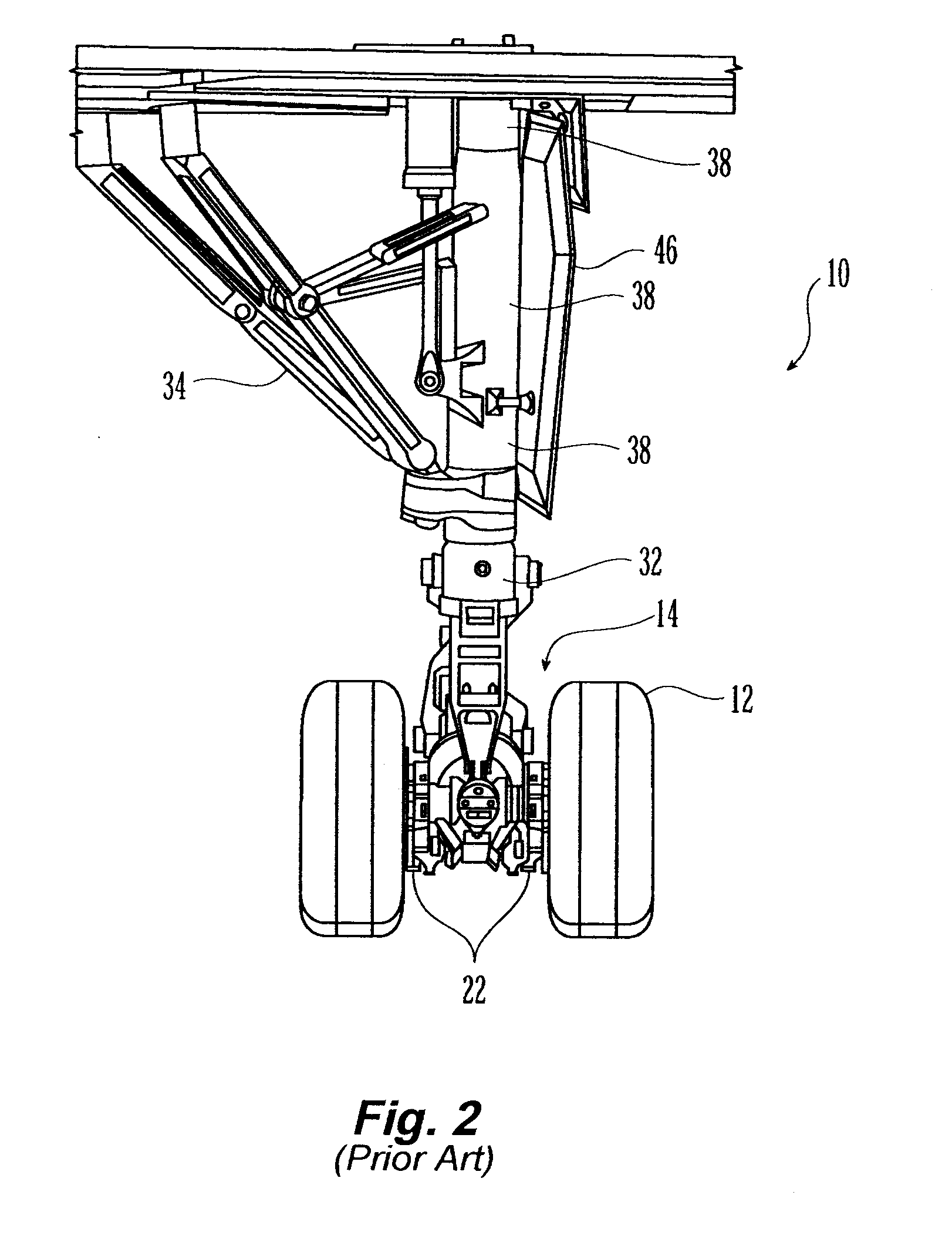
[0059]FIGS. 1, 2 and 3 illustrate a conventional main landing gear 10. For ease of illustration, certain cable harnesses and hydraulic lines are not shown. Landing gear 10, shown in a deployed position, includes wheels 12, axles 14, trucks or bogie beams 18, brakes 22, cable harnesses (not shown), torque links 30,...


PUM


Abstract

A landing gear noise attenuator mitigates noise generated by airframe deployable landing gear. The noise attenuator can have a first position when the landing gear is in its deployed or down position, and a second position when the landing gear is in its up or stowed position. The noise attenuator may be an inflatable fairing that does not compromise limited space constraints associated with landing gear retraction and stowage. A truck fairing mounted under a truck beam can have a compliant edge to allow for non-destructive impingement of a deflected fire during certain conditions.

Description

RELATED APPLICATIONS[0001]The present application claims priority to U.S. Provisional Patent Application No. 60 / 557,236, filed Mar. 29, 2004 and U.S. Provisional Patent Application No. 60 / 641,246, filed Jan. 4, 2005. The contents of these two provisional applications are incorporated by reference in their entirety.STATEMENT REGARDING FEDERALLY SPONSORED RESEARCH[0002]Some aspects of the inventions described in this patent application were made in the performance of work under NASA Contract No. NAS1-03008 and may be subject to the provisions of Section 305 of the National Aeronautics and Space Act of 1958 (42 U.S.C. 2457).FIELD OF THE INVENTION[0003]This invention relates to landing gear noise attenuation and more specifically to apparatus intended to mitigate airframe landing gear noise.BACKGROUND[0004]The interaction of airflow with an airframe's protrusions and cavities creates airframe noise. While engine noise dominates aircraft noise at takeoff, the airframe noise created by la...

Claims


Application Information

Patent Timeline
Patent Type & Authority Patents(United States)
IPC IPC(8): B64C25/00B64C25/34
CPCB64C7/00B64C25/34B64C2025/003Y10T137/36
Inventor MOE, JEFFREY W.WHITMIRE, JULIAKWAN, HWA-WANABEYSINGHE, AMAL
Owner THE BF GOODRICH CO
Why Eureka
Try Eureka