Power supply system and vehicle including the same

a power supply system and power supply technology, applied in the direction of battery/fuel cell control arrangement, electric devices, transportation and packaging, etc., can solve the problems of not meeting the power requirement of a load device (such as a motor), the charge/discharge characteristic of the battery is susceptible to temperature, and the combination of a plurality of batteries different in the full charge capacity cannot be permitted, so as to suppress the influence of electric power supplied/received, the effect of raising the temperature of the power storage uni

Inactive Publication Date: 2011-06-07
TOYOTA JIDOSHA KK
View PDF20 Cites 16 Cited by
  • Summary
  • Abstract
  • Description
  • Claims
  • Application Information

AI Technical Summary

Benefits of technology

[0012]According to one aspect of the present invention, when the actual value of electric power supplied / received to / from the load device is smaller than the total value of the allowable power of the power storage units, one voltage conversion unit is controlled such that the voltage value of the power line attains a prescribed voltage target value (voltage control mode), whereas the remaining voltage conversion units are controlled such that the current values of the power storage units attain prescribed current target values respectively (current control mode). Therefore, the current value, that is, charge / discharge power, of the power storage unit corresponding to the voltage conversion unit controlled in the current control mode can be managed with high accuracy. In addition, the voltage conversion unit controlled in the voltage control mode attempts to maintain the voltage value of the power line at the voltage target value. Accordingly, even if the electric power supplied / received to / from the load device fluctuates, the charge / discharge power of the power storage unit connected to the voltage conversion unit is adjusted in accordance with fluctuation in the electric power. Therefore, power requirement of the load device that fluctuates can also be met. Power management of the power storage unit can thus be realized while the power requirement of the load device is met.
[0028]According to the present invention, a power supply system capable of power management in each power storage unit with high accuracy while meeting power requirement of the load device in accordance with the electric power supplied / received to / from the load device and a vehicle including the power supply system can be realized. In addition, according to the present invention, a power supply system capable of raising a temperature of a power storage unit while suppressing influence on electric power supplied / received to / from a load device and a vehicle including the power supply system can be provided.

Problems solved by technology

Meanwhile, as the power storage unit stores electric energy utilizing electrochemical process, the charge / discharge characteristic thereof is susceptible to a temperature.
Nevertheless, the power control system disclosed in U.S. Pat. No. 6,608,396 has not considered the allowable power of each battery.
Therefore, power requirement in a load device (such as a motor) has not been met.
In addition, since the power control system disclosed in U.S. Pat. No. 6,608,396 is premised on the same fill charge capacity of the battery as designed, combination of a plurality of batteries different in the full charge capacity has not been permitted.
Therefore, running performance of the vehicle has been restricted by execution of control for temperature increase in the battery.

Method used


Image

  • Power supply system and vehicle including the same
  • Power supply system and vehicle including the same
  • Power supply system and vehicle including the same

Examples


first embodiment

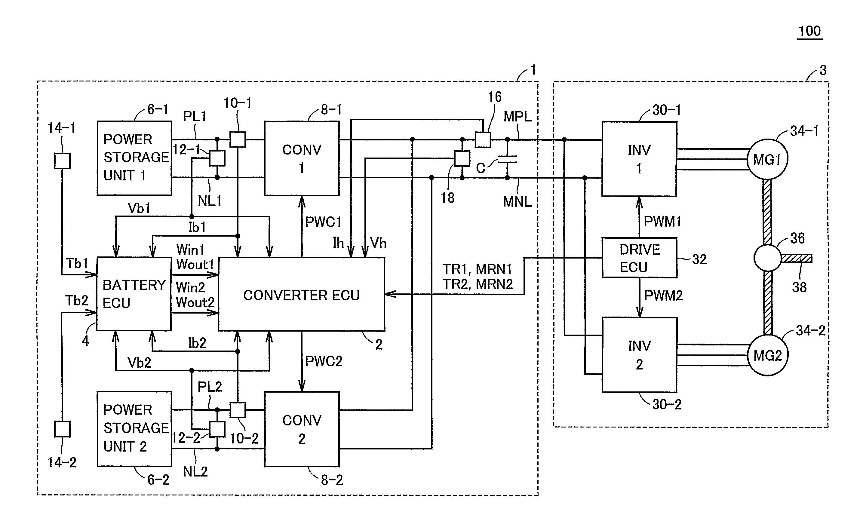
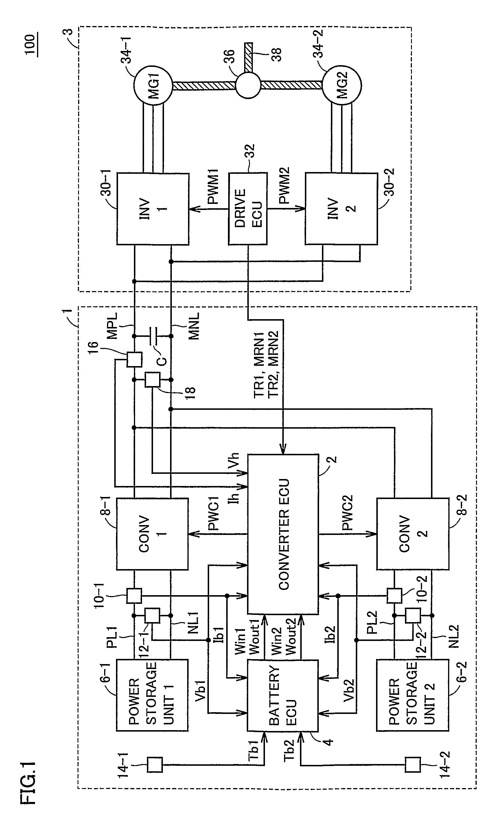
[0050]FIG. 1 illustrates a first embodiment in which a drive force generation unit 3 generating drive force of a vehicle 100 serves as a load device. Vehicle 100 runs by transmitting to drive wheels (not shown), drive force generated from the electric power supplied from a power supply system 1 to drive force generation unit 3. In addition, during regeneration, vehicle 100 causes drive force generation unit 3 to generate electric power from kinetic energy and recovers the electric power in power supply system 1.

[0051]In the first embodiment, power supply system 1 including two power storage units will be described as an example of a plurality of power storage units. Power supply system 1 supplies / receives DC power to / from drive force generation unit 3 through a main positive bus MPL and a main negative bus MNL. In the description below, the electric power supplied from power supply system 1 to drive force generation unit 3 is also referred to as “drive power”, and the electric power...

second embodiment

[0163]In the first embodiment described above, the power supply system capable of power management in each power storage unit with high accuracy while satisfying the power requirement of drive force generation unit 3 has been described. Meanwhile, in the second embodiment below, a power supply system capable of raising a temperature of the power storage unit while suppressing influence on the electric power supplied / received to / from the load device will be described.

[0164]Referring to FIG. 11, a vehicle system 100A includes a power supply system 1A and drive force generation unit 3. Power supply system 1A is equivalent to a system where a converter ECU 2A and a battery ECU 4A are arranged instead of converter ECU 2 and battery ECU 4 in power supply system 1 according to the first embodiment shown in FIG. 1. As other parts of power supply system 1A and drive force generation unit 3 have been described above, detailed description will not be repeated.

[0165]Battery ECU 4A determines wh...


PUM


Abstract

A converter ECU (2) obtains allowable power total value including at least one of discharge allowable power total value ΣWout of discharge allowable power Wout1, Wout2 and charge allowable power total value ΣWin of charge allowable power Win1, Win2. Then, the converter ECU (2) determines which of the allowable power total value and an actual power value is greater, If the actual power value is smaller than the allowable power total value, the converter ECU (2) controls a converter (8-1) such that an input / output voltage value Vh attains a prescribed target voltage value, and at the same time controls a converter (8-2) such that a battery current value Ib2 attains a prescribed target current value.

Description

TECHNICAL FIELD[0001]The present invention relates to a power supply system having a plurality of power storage units and a vehicle including the power supply system, and more particularly to a technique for realizing power management in each power, storage unit with high accuracy in accordance with electric power supplied / received to / from a connected load device. In addition, particularly, the present invention relates to a technique for realizing temperature management of a power storage unit while suppressing influence on electric power supplied / received to / from a load device.BACKGROUND ART[0002]Recently, considering environmental issues, attention has been paid to a vehicle employing a motor as a drive power source, such as an electric vehicle, a hybrid vehicle and a fuel cell vehicle. Such a vehicle includes a power storage unit implemented, for example, by a rechargeable battery or an electric double layer capacitor for supplying electric power to the motor, and converting kin...

Claims


Application Information

Patent Timeline
Patent Type & Authority Patents(United States)
IPC IPC(8): B60L1/00
CPCB60L11/1868B60L11/1875B60L15/2045H02M3/1584Y02T10/7283Y02T10/7005Y02T10/7066B60L58/20B60L58/27Y02T10/64Y02T10/70Y02T10/72B60K6/28B60W10/24B60W20/00
Inventor ICHIKAWA, SHINJIISHIKAWA, TETSUHIROSAWADA, HIROKIOYOBE, HICHIROSAIANG, WANLENGYOSHIDA, HIROSHI
Owner TOYOTA JIDOSHA KK
Why Eureka
Try Eureka